LANGUAGE


In a flower-basket cantilever scaffolding system, every component earns attention in proportion to its size except the one that matters most at the connection. The diagonal tie rod gets the design calculation, the H-section beam gets the specification sheet, and the anchor fitting that joins them, a steel plate smaller than a hand, carries the full tension of the system through a single pin. That fitting is the twin-ear anchor, and its geometry, welds, and pin connection decide whether the calculated load path actually exists on site.
This guide examines the twin-ear anchor as an engineered component: where it sits in the load path, which three mechanical checks govern its capacity, how manufacturing quality separates a rated fitting from a shaped piece of plate, and what site crews and procurement teams should verify before the first tie rod is tensioned.
Direct Answer: What is a twin-ear anchor in cantilever scaffolding?
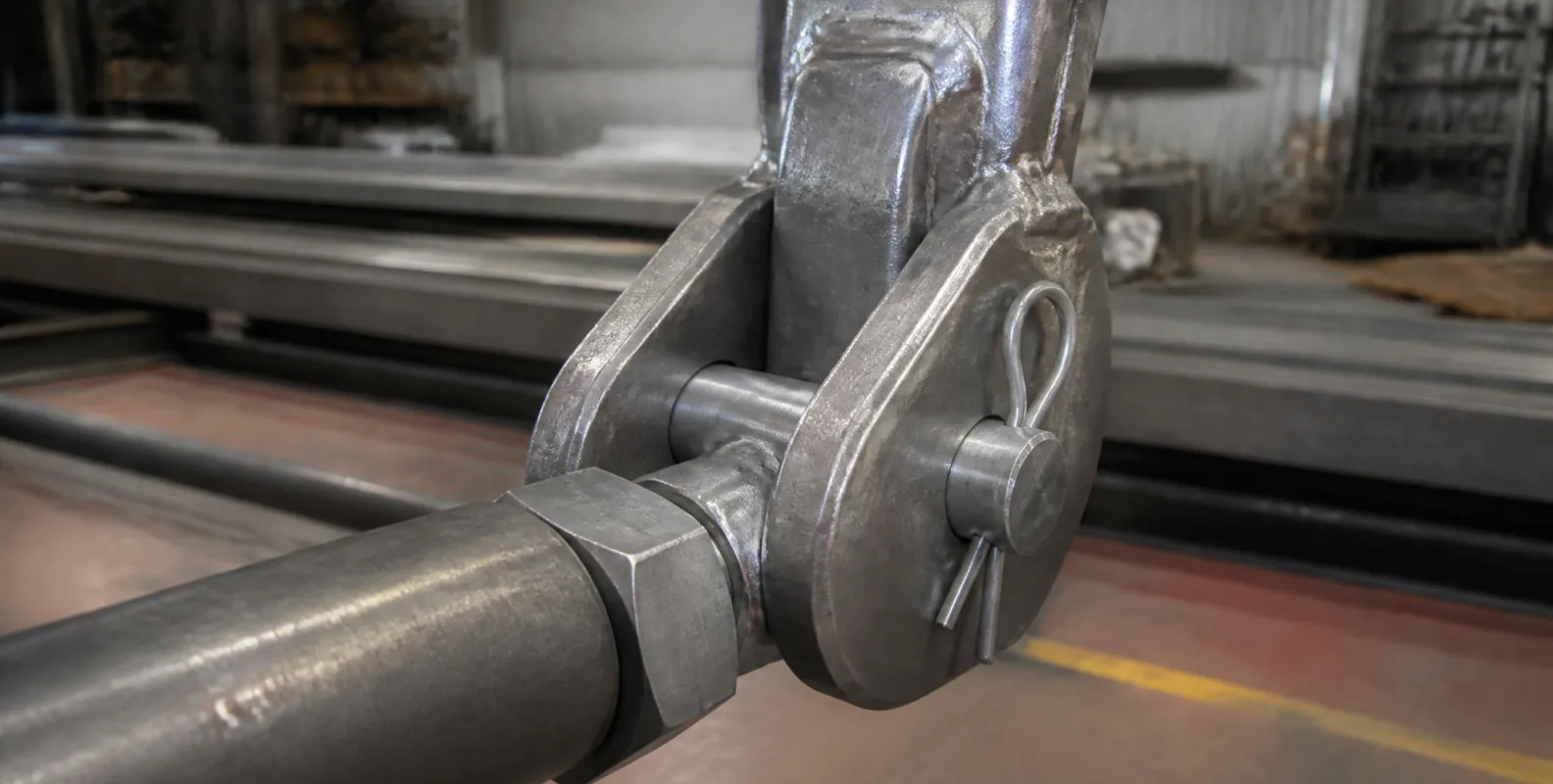
A twin-ear anchor is a steel connection fitting with two parallel lugs (ears) drilled with a common pin hole, used in cantilever scaffolding systems to connect diagonal tie rods to the main cantilever beam or to the building structure. The tie rod end sits between the two ears and is locked by a cross pin, so the rod's tensile force transfers through the pin in double shear and then through the anchor body into the beam or slab. Because the load enters symmetrically from both sides, the twin-ear geometry eliminates the bending that bends and tears single-lug connections under cyclic tension.
Position in the load path
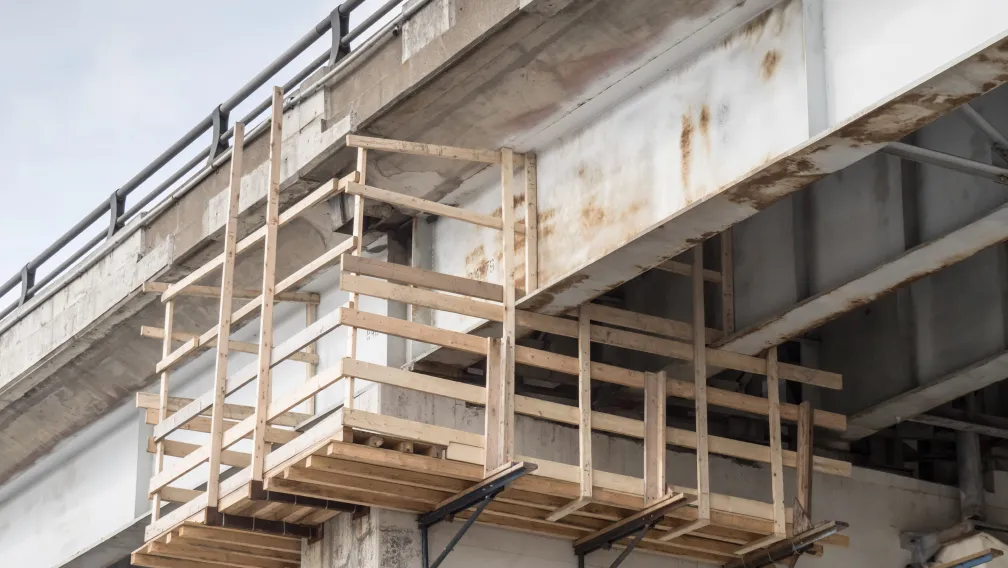
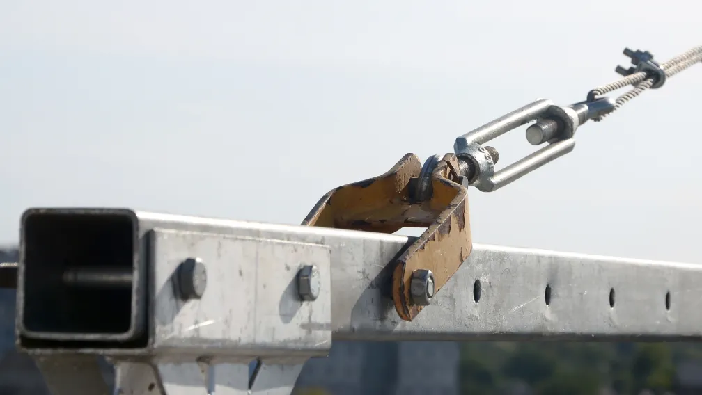
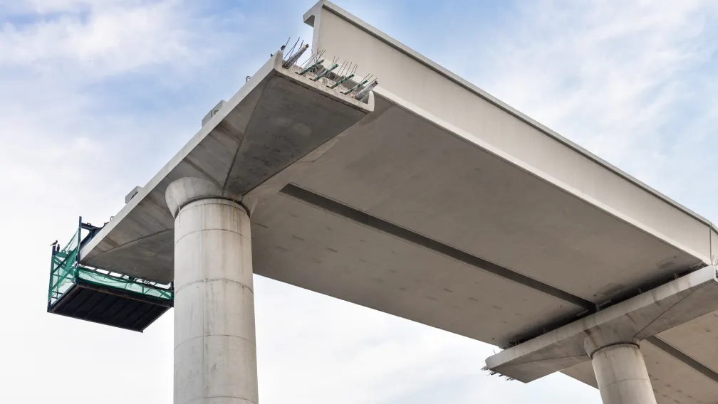
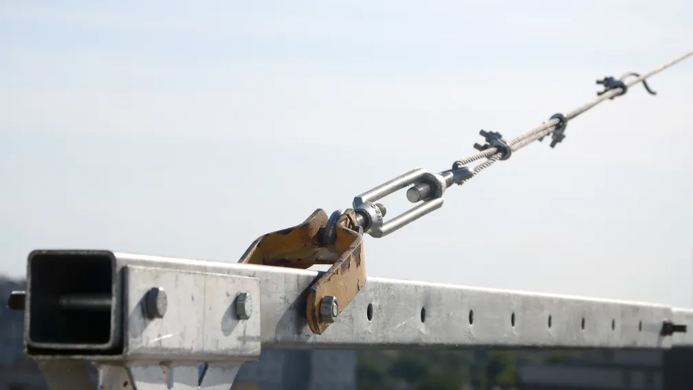
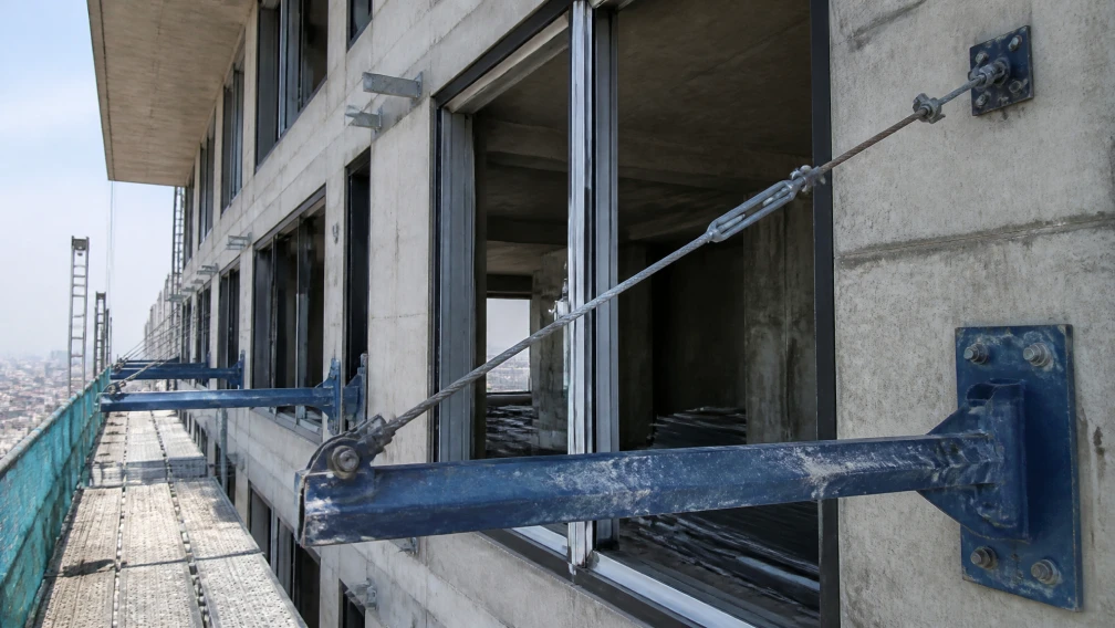
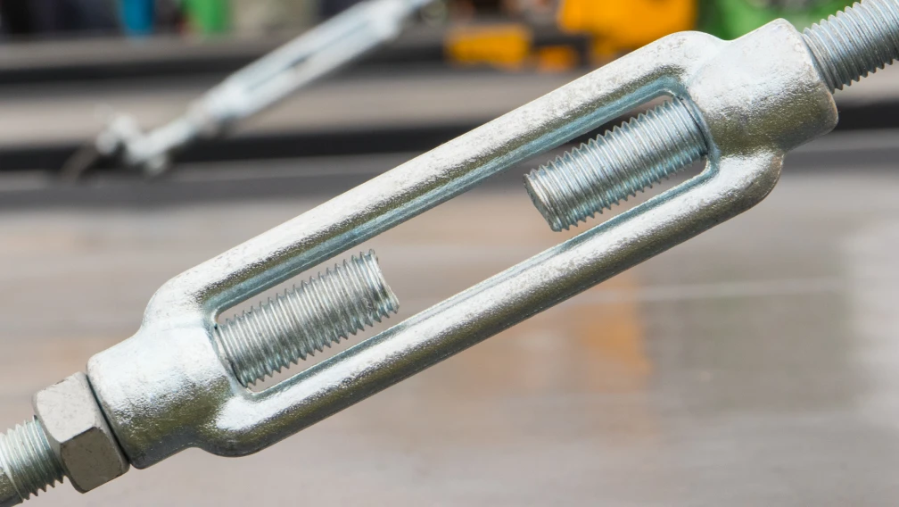
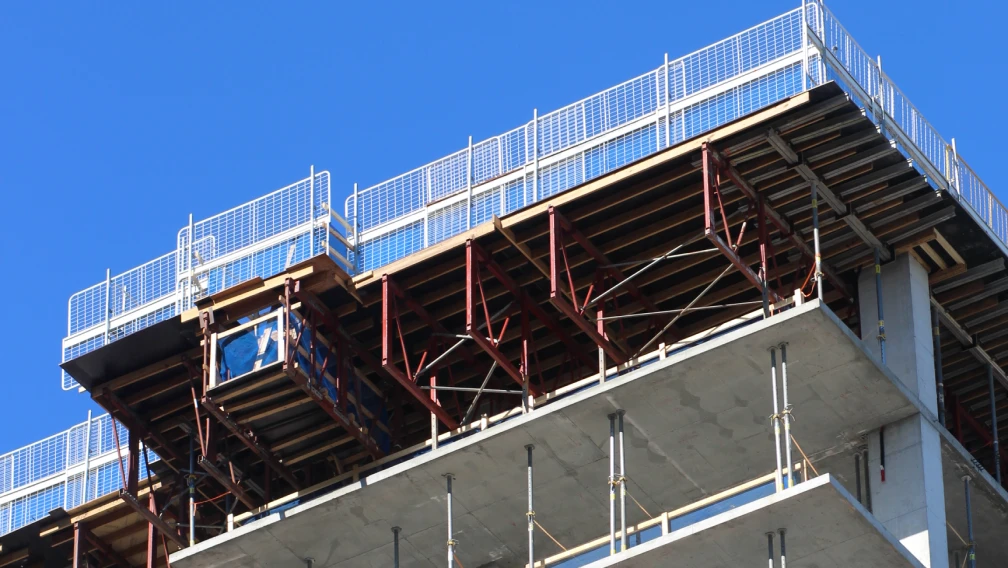
The flower-basket cantilever system supports the scaffold platform on a steel beam projecting from the slab edge, and relieves the beam's bending moment with a diagonal tie rod running from the outboard beam end back to the structure above. The twin-ear anchor appears at both ends of that rod. The lower anchor fixes to the cantilever beam flange, the upper anchor fixes to the structural slab or column, and the scaffold tie rod between them, tensioned through a closed-body turnbuckle, completes the triangle. Every kilogram of platform load that the rod relieves passes twice through a twin-ear connection: once at the beam, once at the structure. The anchor is therefore not an accessory to the system; it is the point where the system's safety factor is physically realized.
Anatomy and typical specifications
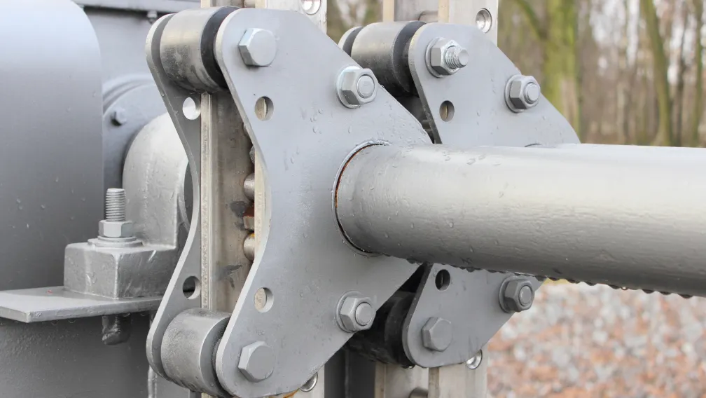
A standard twin-ear anchor consists of a base plate or weld pad, two parallel ear plates, and a matched cross pin with its retaining element. The ear spacing matches the fork width of the tie rod end, the pin diameter matches the rod's rated diameter, and the base plate spreads the anchor force into the host member. Typical production ranges for cantilever duty are summarized below.
| Parameter | Typical range | What it governs |
|---|---|---|
| Ear plate thickness | 10–16 mm per ear | Bearing and tear-out capacity at the pin hole |
| Pin diameter | 20–30 mm | Double-shear capacity of the pin connection |
| Ear spacing (gap) | Matched to rod fork + 1–2 mm clearance | Free articulation without side play |
| Base plate size | Project-specific, 120–250 mm square | Load spread into beam flange or slab |
| Material | Q235B / Q355B structural steel | Weldability and yield strength |
| Surface | Hot-dip galvanized, ISO 1461 | Corrosion life in exposed facade service |
Three mechanical checks that govern capacity
Pin shear
The cross pin works in double shear: the tie rod pulls the middle of the pin while both ears support the ends. Double shear halves the stress per shear plane compared with a single-lug clevis, which is the core mechanical advantage of the twin-ear layout. Pin capacity scales with the square of pin diameter, so a 25 mm pin develops roughly 56 percent more shear area than a 20 mm pin. Pins must be manufactured from the specified steel grade; a soft pin deforms oval in service, locks the joint, and destroys the articulation the connection was designed to allow.
Bearing at the ear hole
The pin presses against the wall of each ear hole, and the plate must carry that contact pressure without deforming the hole. Bearing capacity scales with ear thickness times pin diameter, which is why ear thickness and pin diameter are specified as a matched pair. An elongated or oval hole found at inspection is the physical record of a bearing overload and takes the anchor out of service immediately.
Tear-out from hole to plate edge
The final check is the shear path from the pin hole to the free edge of the ear. Adequate edge distance, in practice an ear that extends well beyond the hole in the load direction, keeps the steel ligament wide enough to resist tear-out. Anchors cut with minimal material around the hole fail this check on paper long before they fail in steel, which is why drawings, not photographs, belong in the procurement file.
Manufacturing quality: what separates a rated fitting from shaped plate
Four production details determine whether a twin-ear anchor performs to its drawing. First, ear parallelism: both ears must sit in the same plane and share a common hole axis, or the pin enters at an angle and loads one ear ahead of the other, converting a double-shear connection into a staggered single-ear failure in progress. Second, hole quality: drilled or reamed holes carry their rated bearing load; flame-cut holes with ragged edges and heat-affected rims concentrate stress and should not reach site. Third, weld quality at the base: the fillet welds joining ears to base plate are the connection's final load path, and they require visual inspection plus non-destructive testing on production samples, since a lack-of-fusion defect hides inside a sound-looking weld. Fourth, galvanizing practice: hot-dip galvanizing after all cutting, drilling, and welding protects every edge, while fittings galvanized before fabrication leave the hole walls and weld toes as bare steel.
Installation and inspection on site
- Confirm the pair. Match the anchor to its designated tie rod by pin diameter and ear gap before lifting; mixed components from different suppliers rarely share tolerances.
- Verify the host member. On the beam end, confirm the anchor welds or bolts to the location on the cantilever I-beam or H-beam shown on the design drawing; on the structure end, confirm the slab anchorage, typically cast-in concrete threaded inserts, has reached the specified concrete strength.
- Align before pinning. The anchor must point along the tie rod's axis. An anchor rotated off-axis forces the rod to bend at the joint and converts pure tension into tension plus prying.
- Seat the pin and retain it. Drive the cross pin fully home and fit its retaining element, whether R-clip, split pin, or lock nut. An unretained pin walks out under vibration.
- Tension and witness. Bring the tie rod to its specified tension through the turnbuckle, then witness-check that the ears show no visible distortion and the pin sits square.
- Register the connection. Enter anchor position, pin size, and tension confirmation in the scaffold inspection record; re-inspect after the first week and after any overload event such as a dropped load or storm.
Common field errors
Site experience with twin-ear connections repeats a short list of mistakes. Undersized pins substituted from general stock pass the hole visually and carry a fraction of the design shear capacity. Anchors mounted off the rod's axis, usually to avoid a clash with deck steel, work in bending instead of tension. Missing retaining clips let pins migrate under the daily vibration of a live scaffold until the joint opens. And re-used anchors with oval holes or ear cracks, retired from one project, reappear on the next when they are not destroyed at withdrawal. Each error is invisible in a photograph and decisive in a failure.
Procurement verification checklist
- Dimensioned drawings. Ear thickness, pin diameter, edge distances, and weld sizes on a signed drawing, not inferred from product photos.
- Material certificates. Mill certificates for plate and pin steel matching the declared grade on the production batch.
- Weld records. Welding procedure specifications and NDT reports on production samples for the ear-to-base welds.
- Load test data. Proof load testing of the complete assembly, anchor plus pin plus rod end, to the stated safety factor above working load.
- Galvanizing after fabrication. Confirmation that HDG follows all machining and welding, with coating thickness verifiable on receipt.
- Matched supply. Anchors, tie rods, turnbuckles, and pins sourced as one verified system, because the load path is only as rated as its least documented component.
Working with Lengge
Lengge manufactures twin-ear anchors together with the tie rods, closed-body turnbuckles, pins, and beam-side fittings that complete the flower-basket cantilever connection, produced in our Hebei facility with mill certificates, weld inspection records, and proof load documentation accompanying every batch. The system ships to contractors and distributors in more than 50 countries.
Send your cantilever layout drawings and design loads through the contact page, and our engineering team will return the anchor specification, matched pin schedule, and quotation for your project.
-

Lengge
Cantilever Scaffolding System Manufacturer
Lengge is a China-based factory producing cantilever I-beams, tie rods, couplers, embedded parts and full scaffolding accessories. We supply contractors, wholesalers and rental companies in over 50 countries from our own production facility in Hebei.