LANGUAGE


The structural vulnerability of end-to-end scaffolding joints
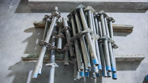
Commercial scaffolding structures routinely exceed 50 meters in height to service high-rise facades and industrial facilities. However, standard steel scaffolding tubes are manufactured and transported in maximum lengths of 6.0 to 6.4 meters due to highway logistics and manual handling limitations on the jobsite. Erecting a continuous vertical standard requires joining multiple tubes end-to-end. Every point where two tubes meet introduces a deliberate mechanical discontinuity into the vertical load path. A poorly executed joint creates a physical hinge point, severely reducing the column's resistance to buckling under compressive dead loads. To bridge this discontinuity safely, site engineers deploy the scaffold sleeve coupler to lock the two tubes coaxially, restoring the structural integrity of the vertical member.
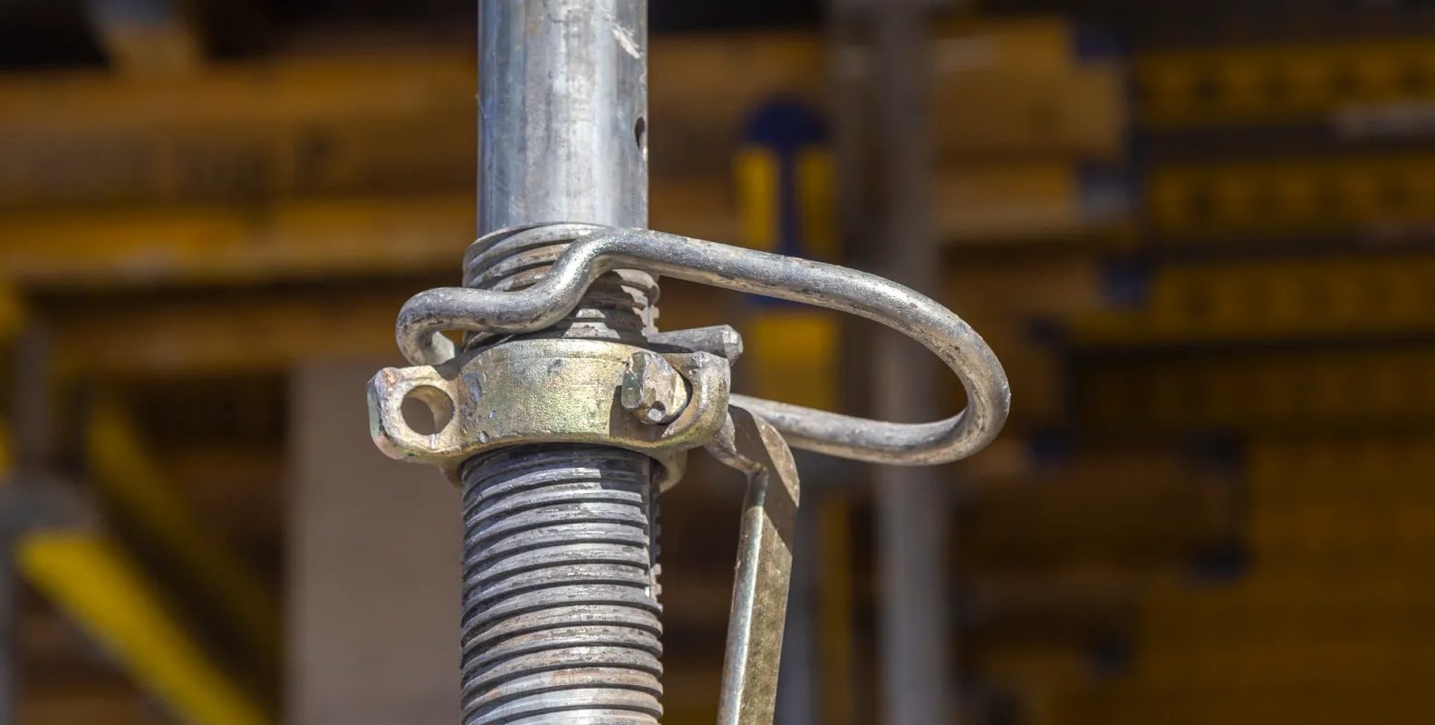
Direct Answer: What is a scaffold sleeve coupler?
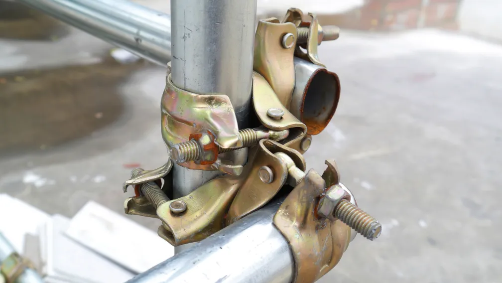
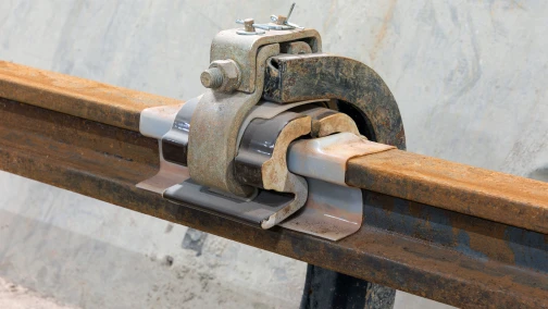
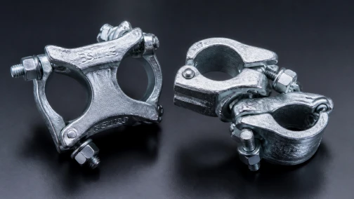
A scaffold sleeve coupler (also known as a joining coupler or external sleeve) is a heavy-duty, drop-forged steel fitting used to connect two 48.3mm outside diameter (OD) scaffolding tubes end-to-end. It features a wraparound tubular body divided into two hinged halves that clamp around the exterior of the abutting tubes. Internally, a central steel locator plate ensures both tubes are inserted to an equal depth. The fitting operates entirely through friction, utilizing two high-tensile Grade 8.8 T-bolts to apply immense clamping pressure. This external connection effectively resists axial tension, compression, and minor bending moments, making it the required jointing method for heavy-duty structural staging.
Axial compression versus bending moments in vertical standards
A continuous vertical scaffold tube (standard) operates primarily under axial compression. The weight of the working platforms, the deposited masonry materials, and the laborers transfers downward through the tube into the base plates. When a joint occurs in this standard, the physical gap between the two tube ends cannot transfer load efficiently. The sleeve coupler wraps around this gap, transferring the compressive force through the friction of the clamped steel.
However, scaffolding networks do not operate in a perfect vacuum of vertical gravity. Wind loads striking the debris netting and uneven loading on the ledgers induce lateral forces into the vertical standards. This translates into bending moments at the joint. If the joint is unsecured, the upper tube acts as a lever and kicks out sideways, triggering a catastrophic buckling failure according to Euler's critical load principles. The extended physical length of a heavy-duty sleeve coupler—typically measuring 210mm to 220mm long—provides sufficient surface contact area across both tubes to resist this lateral bending moment and keep the vertical column perfectly straight.
Internal joint pins versus external sleeve couplers
Contractors face a choice between two distinct methods for joining tubes end-to-end: internal expanding joint pins (spigots) and external sleeve couplers. The mechanical differences dictate their authorized applications.
An internal joint pin slips inside the hollow bore of the 48.3mm tubes. A central bolt expands the pin against the inner wall. While highly aesthetically pleasing and useful for basic compression-only applications, an expanding joint pin offers zero resistance to axial tension. If an upward force is applied, the tubes will immediately pull apart. Furthermore, internal pins offer minimal resistance to bending moments.
Conversely, the external scaffold sleeve coupler clamps around the outside of the tube. This external grip provides massive resistance to axial tension (pull-off forces) and superior rigidity against bending. For external perimeter scaffolds, cantilever scaffolding, and any application subjected to dynamic wind shear, modern engineering codes mandate the use of external sleeve couplers rather than internal joint pins.
The mechanics of the central locator plate
A seemingly minor yet highly engineered feature of a professional sleeve coupler is the central locator plate (or dimple). This is a physical steel obstruction protruding slightly into the inner bore at the exact center of the clamp body.
When a worker inserts the lower scaffold tube into the coupler, the tube stops when it hits this plate. The worker then inserts the upper tube until it contacts the other side of the plate. This guarantees that exactly 50% of the coupler's clamping area grips the lower tube, and 50% grips the upper tube. Without this physical stop, gravity or worker error often causes the coupler to slide down, resulting in a joint where 90% of the clamp grips the bottom tube and only 10% grips the top tube. Such an unbalanced connection possesses negligible slip resistance on the upper tube and will fail immediately under tension.
Drop-forged manufacturing processes and metallurgical grain flow
The structural demands placed on sleeve couplers require flawless manufacturing. As the primary tension-resisting joints in a suspended network, the metallurgical integrity of the clamp body is non-negotiable. Budget suppliers frequently produce sleeve couplers by stamping and rolling thin sheet metal (pressed steel). Pressed steel lacks the required cross-sectional mass. Under high clamping torque or dynamic site vibrations, the pressed steel body stretches, elongating the bolt holes and releasing the frictional grip on the tubes.
Professional scaffolding matrices rely exclusively on drop-forged carbon steel couplers. The drop-forging process begins by heating a solid steel billet to its plastic state. Massive hydraulic hammers compress the heated billet inside precision dies. This extreme compression forces the metallic grain structure of the steel to flow continuously along the exact geometric curves of the clamp body. Drop-forged couplers offer superior tensile strength, extreme resistance to impact shattering, and predictable performance characteristics under heavy commercial loads.
EN 74-1 load ratings and slip resistance benchmarks
To establish a uniform baseline for safety, the global scaffolding industry utilizes the European standard EN 74-1. This regulatory code defines the exact destructive testing methodologies and minimum load requirements for all load-bearing scaffolding fittings.
Under EN 74-1, a heavy-duty drop-forged sleeve coupler is classified under Class B specifications. The rigorous testing parameters determine the component's Safe Working Load (SWL). The table below outlines the expected engineering thresholds for a certified sleeve coupler:
| Technical Parameter | EN 74-1 Class B Specification |
|---|---|
| Tube Outside Diameter (OD) | 48.3 mm |
| Overall Length of Coupler | Typically 210 mm to 220 mm |
| Safe Working Load - Axial Tension | 15.0 kN |
| Safe Working Load - Bending Moment | 1.4 kNm |
| Fastener Standard | Two Grade 8.8 High-Tensile T-Bolts |
Note: These load ratings are entirely dependent on the application of the correct installation torque. Applying inadequate torque nullifies the certified slip resistance of the fitting.
Laboratory testing methodologies for axial tension
Verifying the tensile capacity of a sleeve coupler requires specialized destructive laboratory testing. Procurement teams assessing factory capabilities should review the exact testing protocols documented on the supplier's third-party test reports.
In a standard axial tension test, two 48.3mm steel tubes are connected using the sleeve coupler. The assembly is placed into a heavy hydraulic tensile testing machine. The machine grips the exposed ends of the tubes and begins pulling them apart in opposite directions. Load cells record the exact force applied in kiloNewtons (kN). The test monitors for two failure modes: "slip" and "ultimate failure." Slip occurs when the friction grip yields and the tubes slide out of the coupler body (measured past a strict millimeter threshold). Ultimate failure occurs if the T-bolts snap or the forged cap physically cracks. Certified EN 74-1 Class B couplers consistently demonstrate slip resistance well beyond the 15.0 kN safe working load, absorbing the required safety factors mandated by international construction codes.
Managing tension and pull-off forces in suspended scaffolding
The majority of scaffolding structures bear weight downward into base plates resting on solid ground. However, suspended scaffolding (or hanging scaffolding) operates in reverse. In offshore oil platform maintenance, under-bridge structural repairs, and multi-story atrium finishing, scaffolding networks are hung downward from overhead structural steel beams.
In a suspended setup, gravity acts to tear the vertical standards apart. Every joint in a hanging standard represents a critical tension node. The lower tube, along with the platforms, workers, and materials attached to it, hangs entirely from the frictional grip of the sleeve coupler connecting it to the upper tube. This scenario explicitly forbids the use of internal joint pins. Site engineers calculate the aggregate dead and live loads of the suspended bays below each joint to ensure the total downward force remains well below the 15.0 kN tensile limit of the drop-forged sleeve coupler.
The critical engineering rule: Staggering standard joints
Procuring high-quality sleeve couplers solves only the hardware aspect of structural safety. Site erection methodologies govern the rest. A critical error in scaffolding construction involves placing multiple sleeve coupler joints at the exact same horizontal elevation across adjacent standards.
If the joints on the inner row of standards and the outer row of standards all align at the 6.0-meter mark, the entire scaffolding facade develops a continuous horizontal hinge line. A severe wind gust striking this line can cause the entire upper half of the scaffold to bend and fold over. Strict engineering codes (such as BS 5975 and TG20 guidelines) mandate that joints must be staggered. If the first standard has a joint at 6.0 meters, the adjacent standard must utilize a shorter starter tube (e.g., 4.0 meters) so its joint occurs at 4.0 meters, and the next at 10.0 meters. This vertical staggering ensures continuous, un-jointed steel tubes always bridge the horizontal lines adjacent to any sleeve coupler, preventing the formation of a weak hinge plane.
Interaction with double couplers and node point proximity
The placement of the sleeve coupler relative to the primary orthogonal nodes severely affects its resistance to buckling. The node point is the exact location where a vertical standard intersects with a horizontal ledger and is clamped by a scaffold double coupler.
Structural engineering principles dictate that sleeve coupler joints must be located as close to a node point as physically possible—typically within 300mm of the double coupler. The horizontal ledger restrains the vertical standard from moving laterally. By placing the joint near this restrained node, the bending moments exerted on the sleeve coupler are minimized. If a worker mistakenly places a sleeve coupler joint precisely midway between two ledgers (at the center of the unbraced vertical span), the joint will experience maximum bending stress under compression, drastically increasing the risk of column buckling.
Installation torque mechanics: The 50 Nm standard
Sleeve couplers lack any mechanical interlocking pins that pass completely through the scaffolding tube. They rely 100% on clamping friction. Therefore, the tension applied to the fasteners dictates the structural viability of the joint. Standard EN 74 compliance requires the Grade 8.8 T-bolts to be tightened to a specific torque of 50 Nm (Newton-meters).
At 50 Nm, the cold-rolled threads of the T-bolt draw the hinged caps of the sleeve coupler tightly around the tube. The serrated interior channels of the forged steel bite into the galvanized surface of the tube, generating the necessary friction coefficient. A deviation in this torque directly degrades the safe working load. Under-torquing leaves the connection loose, inviting micro-slip under dynamic vibration. Once the joint slips initially, the kinetic energy spikes, often tearing the tubes completely out of the coupler.
The dangers of pneumatic impact wrenches and thread yielding
The most pervasive threat to scaffolding hardware longevity and site safety is the unregulated use of pneumatic or battery-powered impact wrenches by erection crews. In an effort to increase erection speed, workers use heavy impact drivers to tighten the collared nuts on sleeve couplers, scaffold swivel couplers, and double couplers.
An uncalibrated impact driver can deliver well over 150 Nm of torque in less than three seconds. This extreme over-torquing stretches the steel shaft of the T-bolt beyond its elastic limit. The steel yields and permanently deforms. The nut may feel tight, but the bolt has lost its clamping elasticity. Under the next thermal contraction cycle or heavy dynamic load, the stretched bolt will simply snap. Site management must mandate the use of calibrated manual torque wrenches or digitally limited impact tools that shut off exactly at 50 Nm.
Surface friction coefficients and the impact of wet paint or rust
The mathematical models determining a sleeve coupler's 15.0 kN tensile capacity assume optimal surface conditions. The friction coefficient requires bare galvanized steel pressing against bare galvanized steel. Real-world construction environments routinely introduce surface contaminants that alter this friction coefficient.
If scaffolding tubes are coated in wet paint, thick grease from crane cables, or heavy layers of wet cement paste, the friction coefficient drops precipitously. The tightening torque forces the coupler to clamp down onto a lubricating layer rather than the solid steel tube. In these conditions, a joint rated for 15.0 kN may slip at 5.0 kN. Similarly, heavy flaky rust scaling on un-galvanized tubes crumbles under clamping pressure, reducing the effective tube diameter and loosening the joint. Site supervisors must ensure that tube ends are wiped clean of heavy contaminants before securing the sleeve coupler.
Hot-dip galvanizing (HDG) versus electroplating for long-term rental
Scaffolding couplers are heavy capital investments for rental companies and civil contractors. A standard drop-forged sleeve coupler is expected to remain in active rotation for up to ten years. Protecting the central hinges, the internal serrations, and the T-bolt threads from atmospheric corrosion is paramount to achieving this lifespan.
Electro-galvanizing (zinc plating) deposits a microscopic layer of zinc (10-15 microns) onto the steel. While this provides a shiny, aesthetically pleasing finish for warehouse storage, it quickly wears away under the abrasive handling of an active jobsite. Once the zinc is scratched off, the underlying carbon steel rusts rapidly. Rust binds the central hinge, making the coupler impossible to open and fit around a tube.
Hot-Dip Galvanizing (HDG) is the mandatory specification for professional fleets. The fully assembled forged coupler is submerged in a vat of molten zinc at 450°C. This creates a thick, metallurgically bonded zinc-iron alloy coating (ranging from 60 to 80 microns deep). This heavy-duty layer absorbs physical impacts and completely seals the internal hinge mechanisms against coastal salt-fog and alkaline cement water, ensuring the coupler remains fully operational across dozens of heavy construction cycles.
Fleet maintenance: Inspection protocols for sleeve couplers
Maintaining a massive inventory of scaffolding hardware requires strict demobilization and inspection protocols at the scaffolding yard. When sleeve couplers return from a long-term project, they must undergo physical evaluation before returning to active inventory.
Yard operatives execute a standardized checklist. First, they wire-brush the interior channels to remove hardened concrete paste, which would otherwise reduce the clamping friction on the next deployment. Second, they rotate the hinged caps to ensure free movement; stiff hinges slow down installation labor on the next site. Third, they run the nuts up and down the T-bolts by hand. If the nut binds, it indicates the bolt was stretched by an impact wrench or cross-threaded, and the fastener must be cut out and replaced. Finally, inspectors check the forged body for impact cracks caused by components being dropped from high elevations. Damaged bodies must be permanently scrapped.
Structural calculation inputs: Estimating sleeve coupler quantities
Procurement and logistics planners rely on strict arithmetic rather than guesswork to estimate the necessary hardware quantities for a new scaffolding build. Sleeve couplers scale in direct proportion to the total height of the structure and the bay spacing.
To calculate the required volume, estimators divide the total vertical height of the scaffold by the standard tube length (typically 6.0 meters). This yields the number of joints per standard. They then multiply this by the total number of vertical standards in the scaffold grid. A massive facade scaffold wrapping a 60-meter building will demand thousands of sleeve couplers just to maintain the vertical columns. Buyers add a standard 5% to 8% contingency margin to the final order quantity to account for inevitable jobsite attrition, where small components are frequently lost in mud, buried in concrete debris, or stolen.
B2B procurement specifications and preventing uncertified imports
The international scaffolding trade involves moving thousands of tons of steel components across borders. B2B procurement managers face the constant challenge of filtering out substandard, uncertified hardware marketed at deceptively low prices. Procuring an uncertified sleeve coupler that fails under tension on a suspended offshore scaffold invites catastrophic legal liabilities.
To secure a safe supply chain, commercial buyers must embed strict verification requirements directly into their purchase contracts:
- Demand Third-Party Certification: The supplier must provide official, independent laboratory test certificates confirming the specific coupler model meets EN 74-1 Class B slip and tensile parameters.
- Specify Forging and Marking: Mandate that all bodies and caps are drop-forged carbon steel. Furthermore, the EN 74 standard requires the manufacturer's identifiable mark, the year of production, and the EN standard number to be physically embossed into the forged steel during manufacturing for full traceability.
- Verify Fastener Grades: Require that all T-bolts are stamped with the '8.8' high-tensile designation and utilize cold-rolled threads rather than cut threads.
- Require Mill Test Certificates (MTC): The factory must provide MTCs for the raw steel billets used in the forging process, verifying the exact chemical composition (Carbon, Manganese, Silicon) meets acceptable structural limits.
Connect with our engineering team for certified scaffolding hardware
Lengge Steel manufactures certified, professional-grade scaffolding systems, delivering drop-forged sleeve couplers, double couplers, swivel couplers, and heavy-duty structural steel to tier-one contractors globally. Our production lines enforce strict EN 74 compliance, utilizing Q235B/Q355B drop-forged steel, cold-rolled Grade 8.8 fasteners, and premium hot-dip galvanizing for extended rental lifespans. Submit your project hardware requirements, target quantities, and structural specifications to our engineering desk to receive a comprehensive wholesale quotation and detailed laboratory test documentation. Visit our contact page to secure a highly reliable scaffolding supply chain today.
Frequently Asked Questions
What is the primary function of a scaffold sleeve coupler?
A scaffold sleeve coupler connects two 48.3mm scaffolding tubes end-to-end coaxially. It acts as an external wraparound clamp that bridges the physical gap between the tubes, restoring the structural integrity of the vertical column and providing high resistance to axial tension and bending moments.
What is the safe working load for a certified drop-forged sleeve coupler?
Under EN 74-1 Class B standards, a certified drop-forged sleeve coupler has an axial tension safe working load (SWL) of 15.0 kN and a bending moment SWL of 1.4 kNm, assuming it is installed with the correct tightening torque on clean steel tubes.
Why are external sleeve couplers safer than internal joint pins for suspended scaffolds?
Internal joint pins expand inside the tube bore and offer minimal resistance to pulling forces. In a suspended (hanging) scaffold, the tubes are constantly subjected to axial tension pulling them apart. External sleeve couplers clamp securely over the outside of the tubes, providing massive frictional resistance (15.0 kN) to prevent the tubes from separating under gravity loads.
What is the purpose of the central locator plate inside the sleeve coupler?
The central locator plate acts as a physical stop to ensure that both the upper and lower scaffolding tubes are inserted exactly halfway into the coupler body. This guarantees a balanced 50/50 grip, ensuring optimal friction distribution across both tubes and preventing the coupler from sliding entirely onto one tube during installation.
Why must scaffold sleeve couplers be drop-forged instead of pressed steel?
Drop-forging compresses heated steel billets inside high-tonnage dies, creating a dense, continuous grain structure that follows the geometry of the clamp. This provides superior tensile strength and resistance to impact cracking. Pressed steel sheet metal can easily stretch and deform under the heavy 50 Nm installation torque or dynamic site loads, causing the joint to slip.
What is the correct installation torque for the T-bolts on a sleeve coupler?
The standard installation torque required for the Grade 8.8 T-bolts on an EN 74 certified sleeve coupler is 50 Nm. Using uncalibrated pneumatic impact wrenches is highly dangerous, as it over-torques the bolt, stretching the threads past their yield point and permanently destroying the fastener.
Why must end-to-end joints in vertical standards be staggered?
If all sleeve coupler joints are placed at the exact same horizontal elevation across adjacent vertical standards, the entire scaffold develops a continuous weak hinge line. Staggering the joints vertically ensures that solid, continuous steel tubes always bridge the horizontal lines adjacent to any given joint, preventing the scaffold from buckling or folding under lateral wind shear.
How close should a sleeve coupler joint be to a horizontal ledger?
Structural engineering codes dictate that sleeve coupler joints must be located as close to an orthogonal node point as physically possible, typically within 300mm of the horizontal ledger. The ledger restrains the vertical standard from lateral movement, thereby minimizing the bending moments exerted on the joint.
How does hot-dip galvanizing (HDG) improve the lifespan of sleeve couplers?
Hot-dip galvanizing submerges the forged coupler in molten zinc, creating a thick (60-80 microns) metallurgically bonded zinc-iron alloy coating. This completely seals the external body, the internal channels, the central hinges, and the T-bolt threads against severe atmospheric corrosion, coastal salt-fog, and alkaline cement, allowing the component to survive a 10-year rental lifespan.
What documentation is required to verify the quality of imported sleeve couplers?
B2B procurement managers must request third-party EN 74-1 Class B test certificates verifying slip and tension capacities, Mill Test Certificates (MTC) proving the chemical composition of the raw steel, and visual proof of manufacturer markings and batch numbers embossed onto the forged bodies for complete traceability.
-

Lengge
Cantilever Scaffolding System Manufacturer
Lengge is a China-based factory producing cantilever I-beams, tie rods, couplers, embedded parts and full scaffolding accessories. We supply contractors, wholesalers and rental companies in over 50 countries from our own production facility in Hebei.