LANGUAGE


Steel-framed buildings, industrial plants, and bridge decks share one recurring problem: temporary structures need anchor points on steel beams, but the beams cannot be drilled or welded. A scaffold beam clamp solves this by gripping the flange of a rolled section with a mechanical jaw, converting any accessible I-beam into a rated fixing point for scaffold tubes, hangers, and suspended staging.
This guide covers the main beam clamp types, how rated loads are established under the governing coupler standards, the correct installation sequence on both parallel-flange and tapered-flange sections, and the inspection and procurement points that keep a clamped connection reliable through a full project cycle.
Direct Answer: What is a scaffold beam clamp?
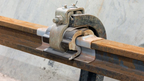
A scaffold beam clamp is a mechanical fitting that clamps onto the flange of a structural steel beam and provides a fixing point for scaffold tubes or suspended loads without drilling, welding, or otherwise altering the beam. Drop-forged beam clamps used in scaffolding are typically rated to slip loads of 15 to 25 kN per fitting under EN 74 testing, accommodate flange widths from roughly 70 to 300 mm, and are installed in opposing pairs so the clamping forces balance across the beam web. The fitting transfers load by friction and positive jaw engagement, so its capacity depends on flange condition and correct tightening torque as much as on the clamp body itself.
Main types of scaffold beam clamps
Fixed-jaw beam clamps (girder couplers)
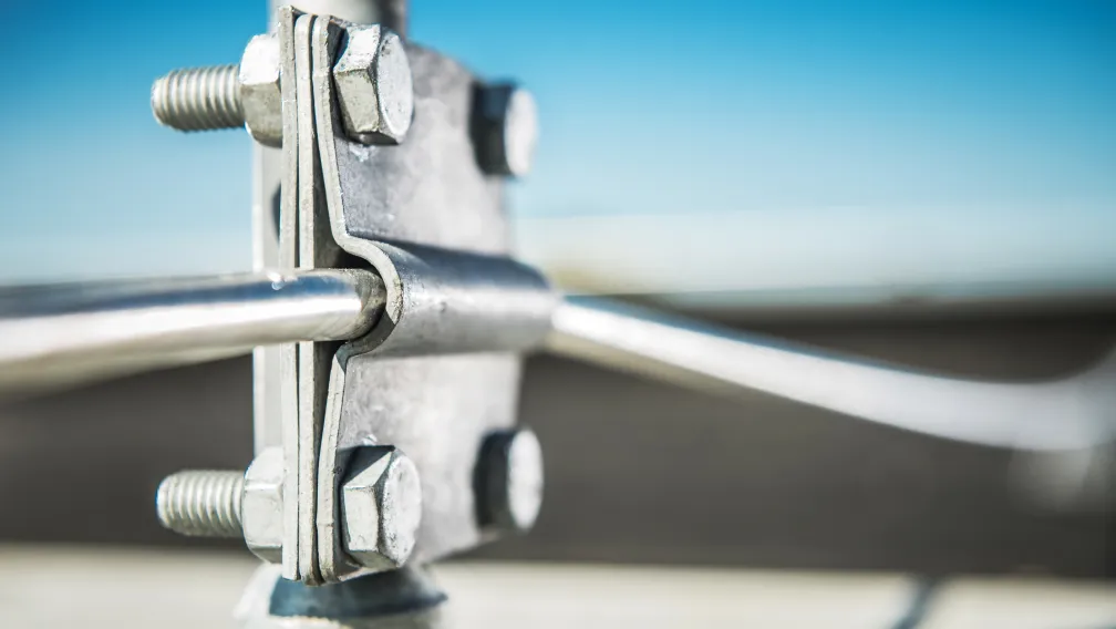
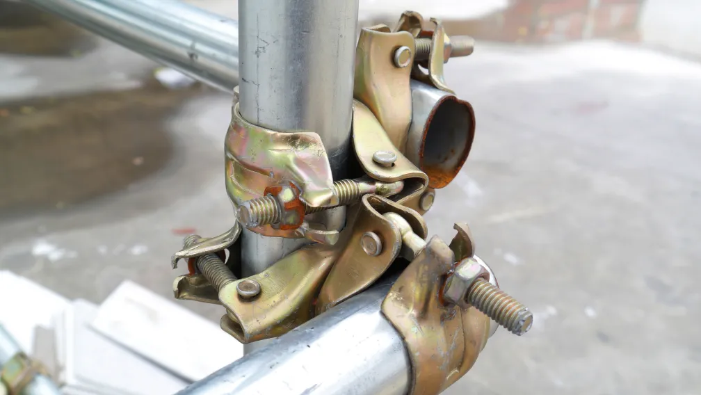
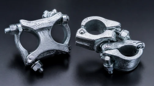
The fixed-jaw girder coupler, often known by the pattern name gravlock, grips the beam flange with a shaped jaw and closes with a bolt or wedge. Once tightened, the jaw locks positively around the flange toe, so the fitting resists both slip along the beam and pull-off away from it. Fixed-jaw couplers accept standard 48.3 mm scaffold tubes at right angles to the beam and form the standard connection for suspended scaffold hangers in UK and Commonwealth practice.
Swivel beam clamps
Where the tube must meet the beam at an angle, a swivel variant replaces the fixed tube seat with a rotating half-coupler. The working principle follows the same logic as a standard scaffold swivel coupler: the rotating jaw accommodates any angle in its plane, while the beam-side jaw keeps its positive grip on the flange. Swivel beam clamps carry lower rated loads than fixed types and serve bracing and non-standard geometry rather than primary suspension.
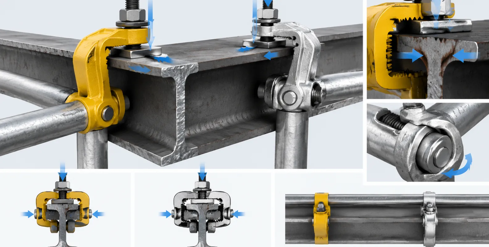
Drop-forged versus pressed steel bodies
Beam clamp bodies divide by manufacturing route. Drop-forged fittings, formed from hot steel in closed dies, offer the grain flow and toughness needed for primary load paths and dynamic site conditions. Pressed-steel fittings, formed from sheet, weigh less and cost less, and suit secondary applications within their rated capacity. For any clamp that suspends a working platform or carries a hanger tube, forged bodies with traceable test certification are the standard specification.
| Type | Connection geometry | Typical rated slip load | Primary application |
|---|---|---|---|
| Fixed-jaw girder coupler | Tube at 90° to beam axis | 20–30 kN per pair (manufacturer data) | Suspended scaffold hangers, staging support |
| Swivel beam clamp | Tube at any angle in plane | Lower than fixed type; bracing duty | Diagonal bracing, non-standard geometry |
| Universal flange clamp | Threaded rod or bolt point, no tube seat | By rod diameter and jaw depth | Suspending services, formwork ties, hangers |
| Wide-throat beam clamp | Adjustable jaw for wide or tapered flanges | Per manufacturer table by flange width | Large universal beams, crane rails, bridge girders |
Rated loads and governing standards
Scaffold fittings in international trade are tested under EN 74 or the closely related BS 1139 series. For right-angle couplers, EN 74-1 defines two performance classes by slip resistance: Class B fittings must sustain 15 kN without slip, and Class A fittings 25 kN. Girder couplers are tested for slip along the flange, pull-off from the flange, and bending at the tube seat, and the manufacturer's declared working load is the governing figure for design. Where a suspended scaffold hangs from beam clamps, the connection is engineered as a system: the clamp pair, the hanger tube, the transverse double couplers at each junction, and the beam itself each carry a share of the verification.
Three factors erode the catalogue rating on a real beam. Paint, rust scale, or oil on the flange cuts the friction component of the grip. Tapered flanges, as found on older rolled sections, tilt the jaw and reduce positive engagement unless the clamp is specified for tapered profiles. And off-axis loading, where the hanger pulls the clamp sideways rather than straight down, introduces prying forces the slip test never simulated. Each of these conditions requires either a correction in the load calculation or a different fitting.
| Verification | Standard reference | What it demonstrates |
|---|---|---|
| Slip resistance along flange | EN 74-1 / BS 1139-2 | Fitting holds rated load without movement |
| Pull-off resistance | EN 74-1 | Jaw retains the flange under separation force |
| Bending at tube seat | EN 74-1 | Coupler body resists rotation failure |
| Material grade | Mill certificate per batch | Forging steel matches declared specification |
| Corrosion protection | ISO 1461 (hot-dip galvanizing) | Coating thickness for outdoor service life |
Installation sequence on site
- Verify the beam. Confirm section size, flange width and thickness, and whether flanges are parallel or tapered. Check the beam's own capacity to carry the imposed point loads with the structural engineer.
- Clean the flange. Remove paint blisters, rust scale, oil, and debris from the jaw contact zones on both flanges.
- Fit clamps in opposing pairs. Place one clamp on each flange so the jaws face inward and the clamping forces balance across the web. A single clamp on one flange leaves the connection free to rotate and walk along the beam.
- Tighten to the specified torque. Scaffold fitting bolts are tightened with a calibrated wrench to the manufacturer's figure, commonly around 50 N·m for standard coupler bolts. Impact drivers without torque control over-tighten and damage threads; under-tightening leaves the slip capacity unproven.
- Connect and plumb the hanger. Seat the 48.3 mm tube in the clamp saddles, tighten the tube-side bolts, and check the hanger hangs plumb so the load enters the beam axially.
- Tag and record. Enter the connection in the scaffold inspection register with location, torque confirmation, and date.
Common failure modes and field errors
Site investigations of clamped-connection failures return the same short list. Clamps fitted singly instead of in pairs rotate under load and migrate along the flange. Jaws seated on thick paint or mill scale slip at loads well below rating, then re-grip unpredictably. Swivel clamps used as primary suspension fittings, outside their design duty, deform at the rotating joint. And re-used fittings with elongated bolt holes or fatigued threads, retired in any competent fleet, quietly re-enter service when procurement buys on price without batch traceability.
A fifth error is geometric: clamping to the tapered flange of an old rolled I-section with a parallel-flange jaw. The jaw contacts the flange toe on a line instead of a face, and the connection holds a fraction of its rated load. Where the structure offers only tapered sections, the specification must call for wide-throat clamps rated for tapered profiles or a different anchorage entirely, such as a sling or an engineered bracket.
Where beam clamps fit in temporary works systems
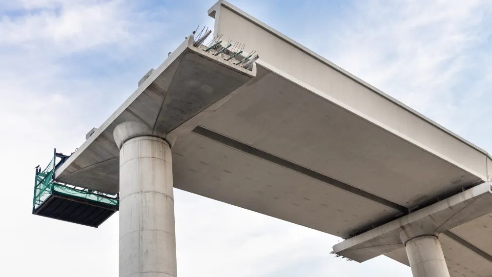
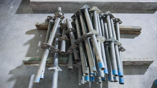
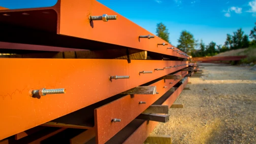
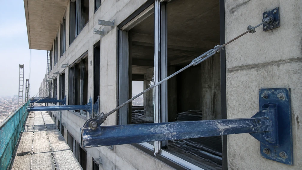
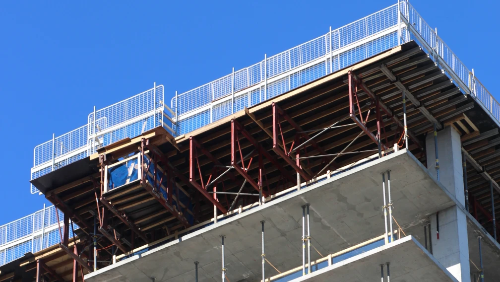
Beam clamps occupy the steel-side counterpart of the concrete-side fixings. On concrete frames, cantilever beams anchor through the slab into cast-in inserts; on steel frames, the same cantilever and suspension loads land on beam clamps gripping the flange. Suspended scaffolds under bridge decks, drop staging in industrial halls, hanger tubes for perimeter protection, and temporary runway supports for adjustable steel prop assemblies all resolve to the same question: which jaw, on which flange, at which rated load. The clamp is also the standard interface where a cantilever scaffolding system bears on an existing steel structure rather than a new concrete edge.
Procurement verification checklist
- Type test certification. EN 74 or BS 1139 test reports covering slip, pull-off, and bending for the exact fitting pattern, issued by an accredited laboratory.
- Declared working loads. Manufacturer tables by flange width and orientation, distinguishing single-fitting and paired-fitting ratings.
- Forging traceability. Mill certificates per production batch, with forging marks on the body matching the certificate reference.
- Dimensional compliance. Tube seat diameter verified at 48.3 mm with go/no-go gauges; jaw opening range checked against the project beam schedule.
- Surface protection. Hot-dip galvanizing to ISO 1461 for outdoor and marine service, with coating thickness verified on receipt.
- Thread and bolt quality. Bolts supplied as matched sets with the fitting, threads gauged, and torque specification stated in the documentation.
Working with Lengge
Lengge manufactures scaffold beam clamps, double and swivel couplers, sleeve couplers, and the wider range of forged and pressed scaffold fittings in our Hebei facility, with batch mill certificates and type test documentation supplied on every order. The range serves contractors, scaffold rental fleets, and distributors in more than 50 countries.
Send your beam schedule, flange profiles, and required working loads through the contact page, and our team will return the clamp specification and quotation matched to your sections.
-

Lengge
Cantilever Scaffolding System Manufacturer
Lengge is a China-based factory producing cantilever I-beams, tie rods, couplers, embedded parts and full scaffolding accessories. We supply contractors, wholesalers and rental companies in over 50 countries from our own production facility in Hebei.