LANGUAGE


Every demountable connection in scaffolding and formwork resolves to a pin. Frames align on them, props lock at height through them, tie rods articulate on them, and anchors release for the next floor by pulling them. Pins are the cheapest components in the connection and the first to be substituted from site stock, which is why they also appear so often in incident reports. A bent positioning pin or a clevis pin of unknown grade converts a rated connection into an assumption.
This guide treats the two pin families used across scaffold and formwork systems as engineered fasteners: what each type does, which mechanical checks govern its capacity, how material and heat treatment separate a rated pin from a rod of unknown steel, and what erection crews and procurement teams should verify before a pinned connection carries load.
Direct Answer: What are positioning pins and clevis pins in scaffolding?
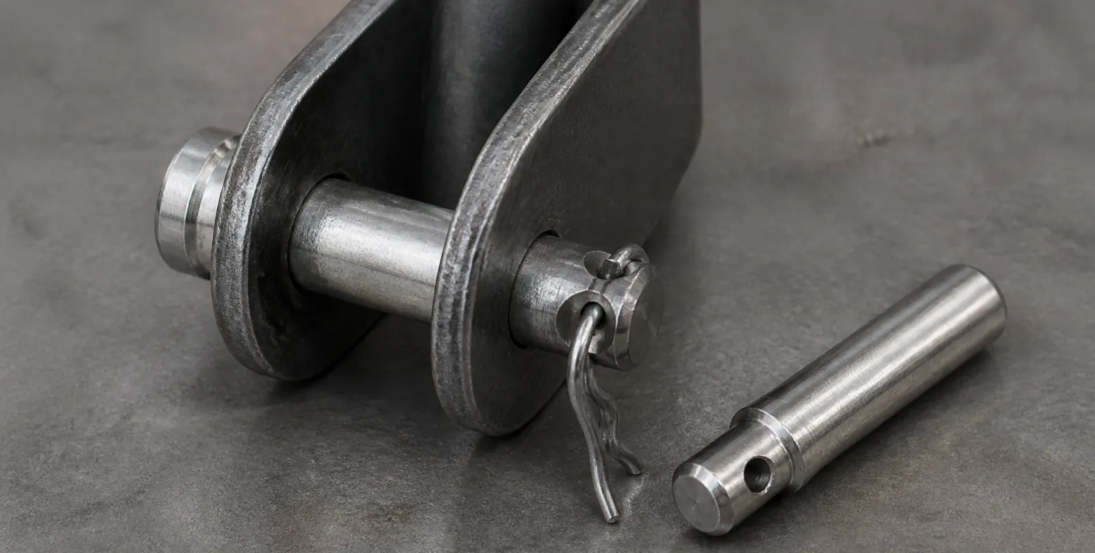
A scaffold positioning pin is a tapered or shouldered steel pin that aligns two components and locks their relative position, carrying alignment and shear duty in frame connections, prop height adjustment, and formwork panel joints. A clevis pin is a headed steel pin with a cross-drilled hole at the opposite end, standardized under ISO 2341, that passes through the ears of a clevis or anchor fitting and is retained by an R-clip or split pin, carrying full tensile connection loads in single or double shear. Both are removable, reusable fasteners whose capacity depends on diameter, steel grade, and correct retention rather than on installation torque.
The two pin families and where each works
Positioning pins
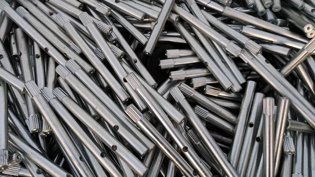
A scaffold positioning pin answers an alignment question. In frame scaffolding it centers the upper frame over the lower and takes the horizontal shear between them; in adjustable props it passes through the height holes of the inner tube and fixes the working length; in formwork it registers panel to panel so the concrete face stays true. The common design features are a taper or shoulder for quick seating, a diameter matched to the hole with minimal play, and a retention element where vibration could walk the pin out. The pin is sized for shear and bearing, and its taper exists for the erector, not the load: a tapered pin seats by hand in a hole that a straight pin would need a hammer to find.
Clevis pins
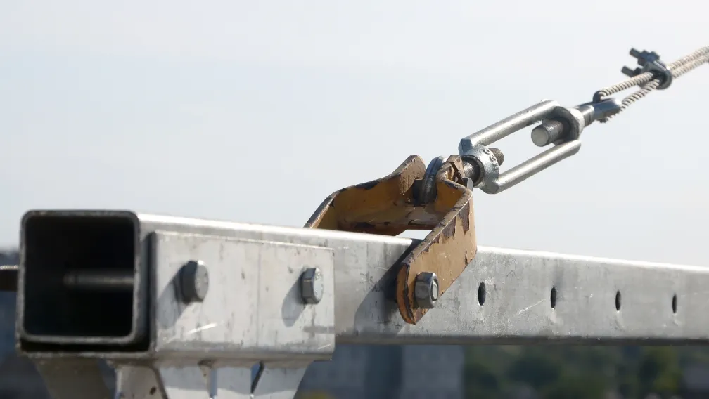
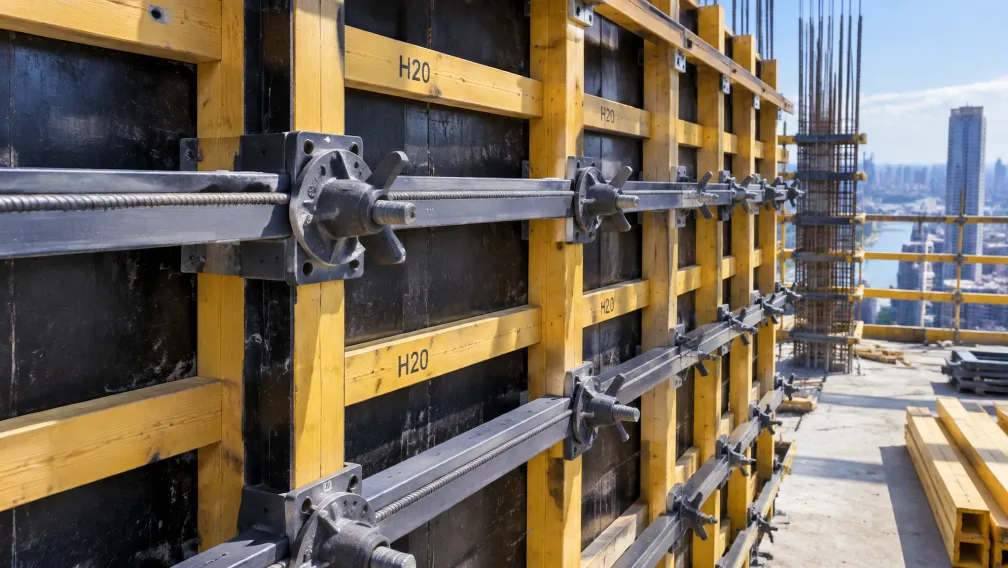
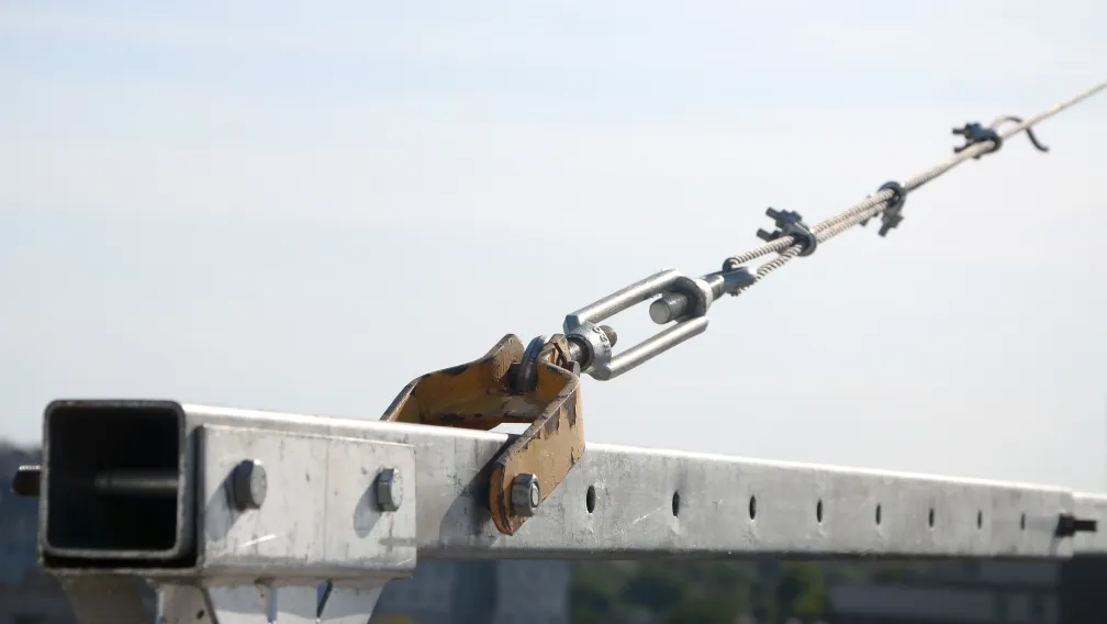
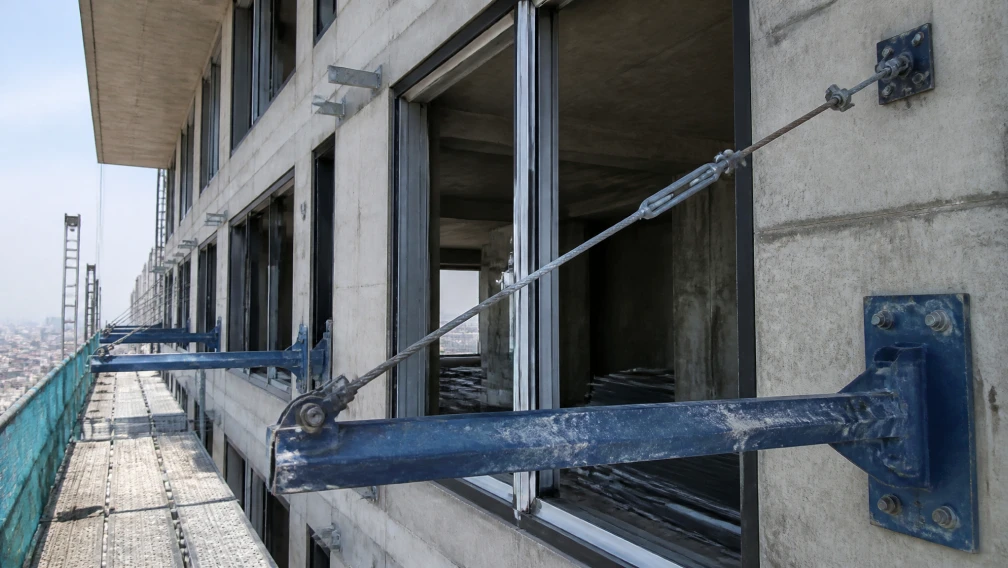
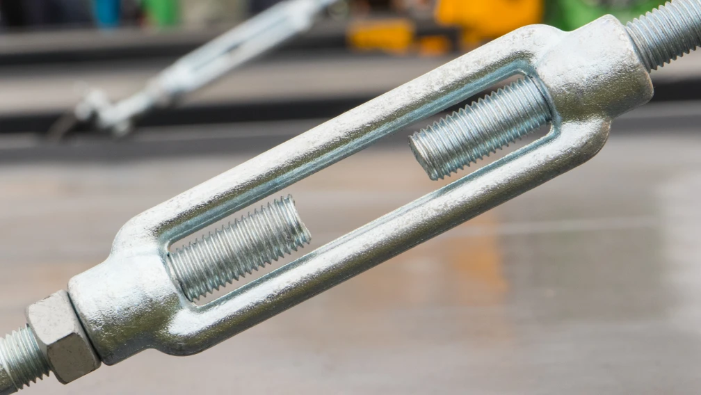
A clevis pin answers an articulation question. Where a connection must carry full structural tension yet remain free to rotate and quick to release, the clevis pin passes through matched ears and locks with a clip through its cross hole. Tie rod ends, turnbuckle forks, twin-ear anchor connections, and brace attachments in cantilever scaffolding systems all resolve to this pattern. The head locates the pin axially on one side, the clip secures it on the other, and the joint articulates freely between the two.
| Attribute | Positioning pin | Clevis pin |
|---|---|---|
| Primary duty | Alignment and shear | Tensile connection with articulation |
| Typical form | Tapered or shouldered shank | Headed shank with cross hole (ISO 2341) |
| Retention | Fit, shoulder, or clip | R-clip or split pin through cross hole |
| Load path | Bearing and shear across the shank | Single or double shear through the ears |
| Typical sizes | 12–25 mm | 16–30 mm |
| Release method | Pull or tap out | Remove clip, withdraw pin |
Mechanical checks that govern pin capacity
Shear across the shank
A pinned connection loads the pin in shear at the interface between the connected parts. Capacity scales with the square of diameter and with the steel's shear strength, and it doubles when the joint works in double shear through two ears instead of one. The practical consequence is unforgiving: a 16 mm pin substituted where the drawing calls for 20 mm carries roughly 64 percent of the designed area, before any question of steel grade is even asked.
Bending in loose joints
Shear calculations assume a tight joint. When the ear gap exceeds the loaded width, or when a worn pin leaves clearance in the hole, the pin spans the gap like a small beam and bending stress adds to shear. Pin bending capacity falls with the cube of diameter, so slight under-sizing and slight looseness compound each other. A pin that can be rattled in its hole by hand is a pin already working outside its design condition.
Retention under vibration
The third check governs nothing about strength and everything about the pin still being there next month. Scaffold and formwork connections live under daily vibration from placing, stripping, and impact. An unclipped clevis pin migrates along its axis until the head side carries the whole joint eccentrically; a positioning pin without its locking element backs out of a prop's height hole and leaves the inner tube free to drop. Retention hardware is part of the rated connection, and its absence at inspection is a defect, not a detail.
Material, heat treatment, and surface protection
Rated pins are manufactured from medium-carbon or alloy steel to a declared grade, with heat treatment where the diameter and duty require it, and with the grade traceable to a mill certificate. The site alternative, a length of round bar cut and drilled by hand, carries none of that: unknown steel, no heat treatment, a flame-cut cross hole with stress-concentrating edges. Surface protection divides by duty. Zinc plating suits protected formwork interiors; hot-dip galvanizing to ISO 1461 suits exposed scaffold service where a seized or wasted pin must still withdraw cleanly years later. Cross holes should be drilled before coating so the hole walls carry protection too.
Installation and inspection on site
- Match pin to hole. Confirm pin diameter against the component drawing or the stamped size on the fitting; never gauge by eye against the hole.
- Inspect before insertion. Reject pins showing shank bending, necking, corrosion pitting on the shear plane, or cross holes with cracked ligaments.
- Seat fully. Drive or press the pin until the head or shoulder seats against the fitting face; a half-seated pin loads on a reduced bearing length.
- Fit the retention. Install the R-clip or split pin through the cross hole and confirm it cannot vibrate free; on positioning pins, engage the locking element the design provides.
- Check articulation. The connected parts should rotate on the pin without side play; binding indicates a bent pin or misaligned ears, and rattling indicates wear.
- Record and re-inspect. Include pinned connections in the routine scaffold or formwork inspection, and re-check after stripping operations and after any impact event.
Common field errors
Site practice generates the same short list of pin failures. Undersized pins pulled from general stock fit loosely and work in bending. Mild-steel bar substituted for rated pins shears at loads the drawing assumed a hardened pin would carry. Missing clips let pins walk out under vibration until a connection opens without warning. Re-used pins with worn shanks and oval cross holes pass visual checks and fail at a fraction of rating. And pins driven into misaligned holes with hammers arrive pre-damaged, their surfaces scored and their steel work-hardened at exactly the section that will carry shear.
Procurement verification checklist
- Dimensional compliance. Diameter, grip length, and cross-hole position to drawing or to ISO 2341 for clevis pins, verified with gauges on sample units.
- Material traceability. Mill certificates confirming the declared steel grade and heat treatment on the production batch.
- Hole quality. Cross holes drilled, not flame-cut, with clean edges; coating applied after drilling.
- Matched retention. Clips and split pins supplied with the pins, sized to the cross hole, not sourced separately by approximation.
- Surface protection. Zinc plating or hot-dip galvanizing specified to the service environment, with thickness verifiable on receipt.
- System supply. Pins delivered as part of the fitting sets they serve, so diameters and tolerances match the ears and holes they will work in.
Working with Lengge
Lengge manufactures positioning pins, clevis pins, and the matched retention hardware for scaffold, formwork, and cantilever system connections, produced in our Hebei facility with material certificates and dimensional records accompanying every batch. Pins ship individually or as part of complete fitting sets with the anchors, tie rods, and turnbuckles they connect.
Send your connection drawings or fitting schedules through the contact page, and our team will return the pin specification and quotation matched to your system.
-

Lengge
Cantilever Scaffolding System Manufacturer
Lengge is a China-based factory producing cantilever I-beams, tie rods, couplers, embedded parts and full scaffolding accessories. We supply contractors, wholesalers and rental companies in over 50 countries from our own production facility in Hebei.