LANGUAGE


The engineering challenge of steel-to-tube connections
In high-rise construction, industrial plant maintenance, and bridge repair, contractors frequently need to attach temporary tubular scaffolding directly to the permanent structural steel frame. Standard practice forbids welding temporary supports to primary load-bearing beams because the extreme heat alters the metallurgical properties of the structural steel. Furthermore, drilling holes through the flanges of a structural I-beam severely weakens its tension and compression capacities. Site engineers resolve this connection challenge by utilizing specialized frictional fastening hardware known as a scaffold beam clamp, also commonly referred to as a girder coupler or SK clamp.
These mechanical couplers create a secure, non-destructive bridge between the flat or tapered flange of a steel beam and a standard 48.3mm outside diameter (OD) scaffold tube. The physical integrity of this node dictates the safety of the entire suspended or cantilevered staging structure. A failure at the beam clamp connection results in immediate and catastrophic platform collapse.
Direct Answer: What is a scaffold beam clamp?
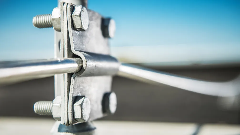
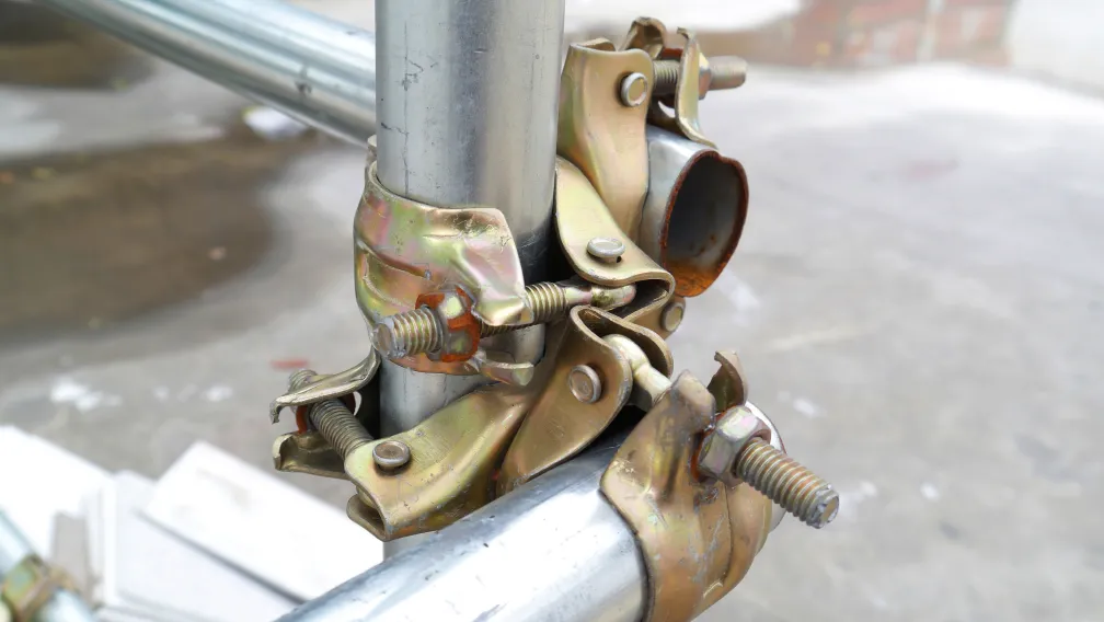
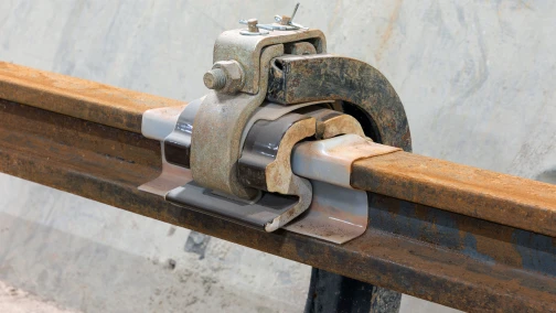
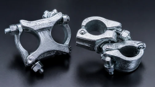
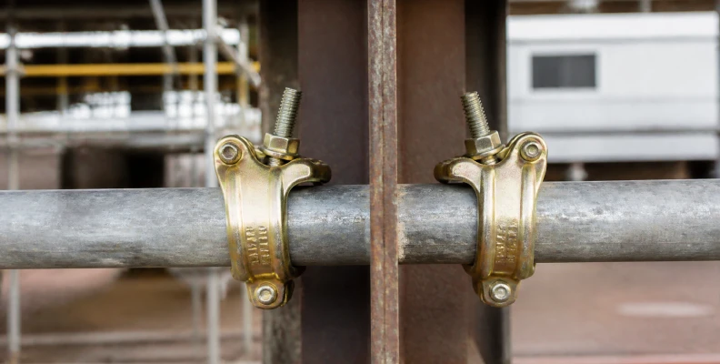
A scaffold beam clamp (girder coupler) is a heavy-duty, drop-forged steel fitting designed to connect a standard 48.3mm scaffold tube to the flange of a structural I-beam or H-beam without welding or drilling. The clamp features a forged body that wraps over the steel flange and a bolted jaw that grips the scaffold tube. They operate entirely through friction and clamping force provided by high-tensile Grade 8.8 T-bolts. To prevent eccentric rotation and ensure structural stability, beam clamps are strictly required to be used in opposing pairs across the same steel flange.
Mechanical design: Why drop-forging is mandatory
When analyzing the mechanical failure paths of a girder connection, the point of highest stress concentrates at the inner throat of the clamp body—the exact point where the clamp bites into the steel flange. Scaffold couplers manufactured through basic casting processes possess a brittle, porous internal microstructure. Under dynamic shock loads or heavy vibration from site machinery, a cast iron clamp can crack and fail instantly without prior plastic deformation.
To guarantee safety, international standards (such as EN 74-1 and BS 1139) require load-bearing beam clamps to be manufactured via drop-forging. The drop-forging process forces heated carbon steel into a shaped die under extreme tonnage. This aligns the metallic grain structure of the steel along the geometric curves of the clamp, providing superior tensile strength and fatigue resistance. A forged steel clamp will yield and stretch visibly if severely overloaded, giving site inspectors a clear visual warning long before ultimate failure occurs.
Load capacities and slip resistance parameters
Scaffold beam clamps do not carry load through a mechanical interlock (like a pin through a hole); they rely entirely on friction generated by bolt torque. Engineering calculations must account for the slip resistance force along the flange and the pull-off force perpendicular to the beam.
Under the EN 74-1 testing parameters for Class B couplers, a pair of heavy-duty beam clamps must demonstrate massive resistance to slippage. The table below outlines the standard baseline engineering parameters for a certified drop-forged girder coupler pair:
| Technical Parameter | Specification / Capacity |
|---|---|
| Standard Tube Compatibility | 48.3mm Outer Diameter (OD) |
| Maximum Flange Thickness Capacity | Up to 45mm (Depending on model) |
| Safe Working Load (SWL) - Slip Resistance | 30.0 kN (Per Pair) |
| Safe Working Load (SWL) - Tension / Pull-off | 15.0 kN (Per Pair) |
| Required Fastener Grade | High-Tensile Grade 8.8 T-Bolt & Nut |
Note: Safe working loads are calculated assuming correct installation torque on clean, dry steel. The presence of oil, wet paint, or heavy rust on the structural beam flange drastically reduces the friction coefficient and lowers the actual slip resistance.
The strict rule of pairing: Preventing rotational failure
The most common and dangerous error in scaffold erection is attempting to secure a scaffold tube using a single beam clamp on one side of a flange. A single clamp provides an unbalanced connection point. When a load is applied to the scaffold tube, the eccentric force creates a massive rotational bending moment. This rotational force will inevitably twist the single clamp right off the steel flange.
Scaffold beam clamps must exclusively be used in opposing pairs. One clamp grips the left side of the beam flange, and the second clamp grips the right side of the same flange. The scaffold tube runs completely across the underside or top of the beam, locked into both clamps simultaneously. This paired configuration neutralizes the rotational forces, converting the dynamic loads of the scaffolding purely into downward pressure and lateral friction across the wide steel flange.
Compatibility with H-section and standard I-beams
Procurement officers must match the design of the beam clamp to the physical geometry of the structural steel on site. High-rise projects utilize different steel profiles that affect how the clamp seats against the metal.
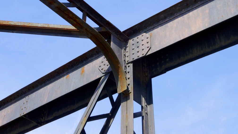
A standard cantilever I-beam (such as a 16# or 18# profile) features a tapered inner flange. The steel gets thicker closer to the central vertical web. Heavy-duty drop-forged beam clamps are designed with a slight internal radius on the biting jaw to accommodate this slope, ensuring maximum surface contact. Conversely, modern H-section steel features flanges that are completely flat and parallel. The jaw of a quality girder coupler will engage flat flanges perfectly, providing a secure, uniform bite. Before purchasing, verify that the clamp's maximum jaw opening capacity exceeds the maximum flange thickness of the heaviest steel member on the project blueprints.
Installation torque specifications and bolt grades
Because the connection relies on friction, the torque applied to the T-bolt dictates the entire mechanical capacity of the node. EN 74 compliant scaffold clamps utilize Grade 8.8 high-tensile steel bolts and specialized collared nuts. The standard required installation torque for a heavy-duty beam clamp is 50 Nm (Newton-meters).
Site supervisors must strictly enforce the use of calibrated torque wrenches rather than pneumatic impact drivers. Impact drivers easily exceed 100 Nm of torque in seconds. Over-torquing stretches the threads of the T-bolt past their elastic limit, inducing micro-fractures in the steel and permanently ruining the fastener. Conversely, under-torquing leaves the connection vulnerable to micro-slip vibrations. Once a clamp slips even a few millimeters under load, the kinetic energy spikes, often tearing the entire assembly away from the flange.
Applications in suspended and cantilever configurations
Beam clamps excel in two primary high-rise applications where building directly up from the ground is impossible.
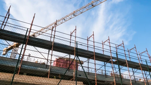
Suspended (Hanging) Scaffolding: In offshore oil rigs, bridge deck maintenance, and high-rise transfer floors, workers construct the scaffold downwards. Pairs of beam clamps grip the upper structural steel framework, and vertical scaffold drop-tubes are suspended from them. These vertical drop-tubes are then laced together horizontally using standard scaffold double couplers to form the working deck in mid-air.
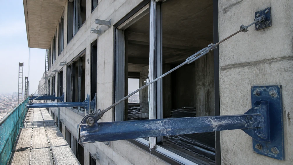
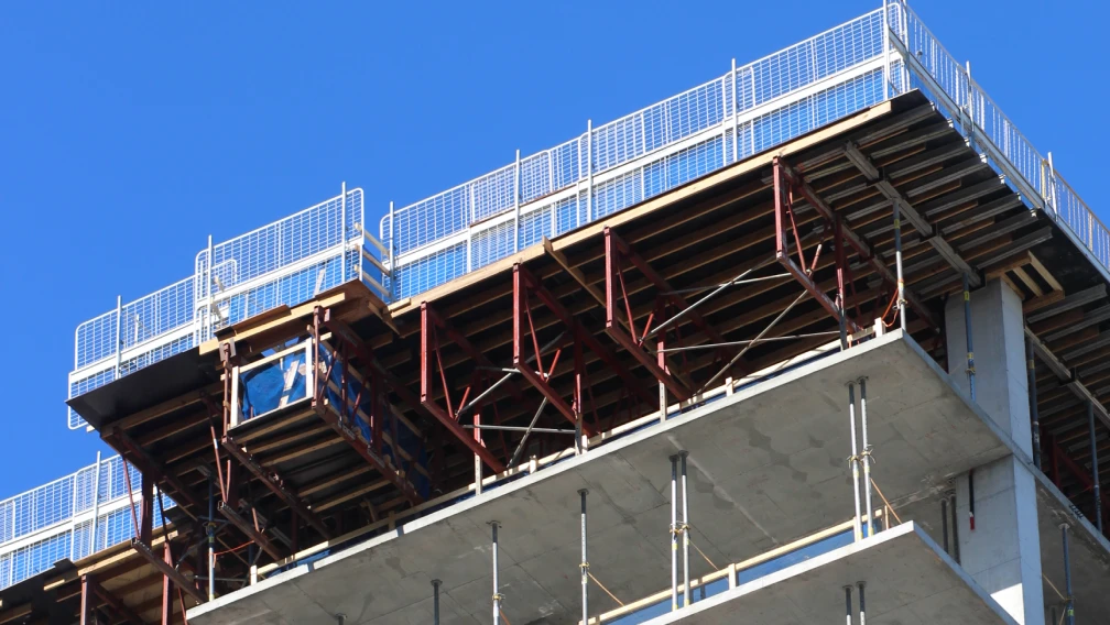
Cantilever Base Securing: When extending temporary platforms out of a building window or edge, the inboard (interior) tail of the cantilever tube must be anchored to prevent the platform from tipping over like a seesaw. If an interior structural floor beam is available, site crews use beam clamps to lock the tail of the scaffold tube directly upward against the bottom flange of the permanent floor beam, creating a completely rigid counterweight anchor.
Surface treatments: Zinc plating vs. HDG
The lifespan of scaffolding hardware is determined by its resistance to environmental corrosion. Construction environments subject fasteners to alkaline cement dust, mechanical abrasion, and constant moisture.
Electro-galvanizing (Zinc Plating) deposits a thin layer of zinc (usually 10 to 15 microns) onto the steel. This provides an aesthetic, bright finish suitable for short-term indoor projects or dry climates. However, for serious outdoor construction, coastal environments, or heavy industrial plant turnarounds, Hot-Dip Galvanizing (HDG) is mandatory. The HDG process immerses the forged clamp into molten zinc, creating a thick (60+ microns), metallurgically bonded zinc-iron alloy layer. This heavy coating absorbs physical impacts from rough handling and provides decades of rust prevention, ensuring the threads of the T-bolt remain free-spinning for multiple project lifecycles.
Procurement guidelines for international B2B buyers
Purchasing load-bearing scaffolding connections based solely on the lowest per-piece price introduces extreme liability to an engineering firm. B2B buyers importing scaffold couplers must enforce strict documentation and quality checks during the procurement process.
- Specify the Standard: Purchase orders must explicitly state compliance with EN 74-1 Class B or BS 1139.
- Demand Forged Verification: Request factory videos or certification proving the bodies and caps are drop-forged carbon steel, not cast iron or pressed sheet metal.
- Check Fastener Quality: The T-bolts and nuts must be stamped with '8.8' indicating high-tensile grade. Lower grade fasteners (like 4.8) will strip under the required 50 Nm of installation torque.
- Request Independent Testing: Suppliers should provide third-party laboratory destruction test reports showing the ultimate slip and pull-off failure points of the exact batch being purchased.
Jaw geometry and the flange thickness window
Every beam clamp is built around a jaw window, and matching that window to the steel on your project is the first selection checkpoint that buyers skip at their peril. Standard girder couplers accept flange thicknesses from roughly 8 mm up to 40 mm, but the jaw geometry differs between models intended for parallel-flange sections and those cut for the tapered flanges of older I-beam profiles. A clamp designed for parallel flanges seated on a tapered beam contacts the steel on a knife edge rather than across the jaw face, concentrating the clamping force into a line that can slip under vibration. The practical verification takes ten minutes: measure the flange thickness and taper angle of the beams on your project, then confirm against the supplier's jaw drawing before ordering. For the heavy H-section steel common in suspended scaffold support frames, confirm that the jaw opening clears the flange width as well as the thickness, because a clamp that fits the thickness but bottoms out on the web never achieves its rated grip.
The physics of slip resistance
A beam clamp holds by friction, and friction is manufactured, not assumed. The clamping force generated by torquing the Grade 8.8 T-bolt to 50 Nm presses serrated jaw faces into the flange steel, and the coefficient of friction between those serrations and the flange surface produces the slip resistance that EN 74-1 verifies at 6.1 kN for Class A and 9.1 kN for Class B. Three site realities degrade this chain. Paint or mill scale on the flange acts as a slip layer, so clamps belong on bare, clean steel. Vibration from concrete placing loosens bolts over days, which is why torque checks enter the weekly inspection routine on suspended applications. And serrations wear smooth across dozens of installations in rental service, silently eroding slip capacity while the clamp still looks serviceable. Fleet managers who gauge jaw serration depth during maintenance catches the third failure mode before it reaches a facade; buyers evaluating used-equipment purchases should treat worn serrations as a price negotiation point, since re-machining jaws is rarely economical.
Load paths in suspended and cantilever applications
The beam clamp earns its keep in two configurations that load it differently, and confusing them underpins most field errors. In suspended scaffolding, pairs of clamps grip a structural beam overhead and hang the working platform below on tubes, placing the clamp jaws in direct tension separation; here the rated safe working load per pair, typically 30 kN for Class B hardware, governs outright, and rigging practice demands independent secondary retention so a single clamp failure cannot drop the platform. In cantilever configurations, clamps tie horizontal tubes to the flanges of cantilever I-beams, loading the jaws in a combination of shear and prying that peaks when workers stand at the platform edge. Both configurations share one rule: the load must enter the clamp along its designed axis. Side-loading a girder coupler with a tube running at an angle to the jaw converts a friction connection into a lever, and the rated capacity printed on the certificate quietly stops applying.
Inspection cycles for clamps in service
A beam clamp is a mechanical device with wearing parts, and treating it as permanent hardware is how accidents get scheduled. The inspection rhythm that rental fleets and safety regulators converge on has three tiers. Before each installation, the installer checks the bolt threads for stretching, the jaws for serration wear, and the body for cracks at the forging parting line, a thirty-second pass that catches most defects. Weekly on suspended applications, a competent person re-verifies bolt torque with a calibrated wrench, because vibration relaxation is predictable rather than exceptional. Between projects, every clamp gets a full strip: bolts and nuts gauged against new hardware, bodies checked for permanent jaw spread with a simple go/no-go gauge, and any unit showing deformation condemned on the spot. Clamps that have survived a documented overload or a dropped load deserve retirement regardless of appearance, since forging cracks that will grow under fatigue are invisible to the eye. Records matter here; a painted inspection date on each clamp, renewed at each strip-down, turns the maintenance program from intention into evidence.
Misuse patterns that site audits keep finding
Audit findings on beam clamps repeat across projects with remarkable consistency. The single-clamp error leads the list: one clamp holding a tube creates an eccentric pivot that rotates under load, which is why standards insist on paired clamps for any load-bearing connection. Cheater bars come second, where installers extend the wrench to compensate for corroded threads, over-torquing the bolt past its elastic range and permanently stretching it; the correct response to a stiff nut is thread lubricant or replacement hardware, not more leverage. Third is the flange mismatch, clamps hung on flanges too thin for the jaw range, where the bolt runs out of travel before full clamping force develops. Fourth is mixed-hardware assemblies, where bolts from one manufacturer meet bodies from another and thread tolerances stack up into a loose fit. Each of these patterns is cheap to prevent at the toolbox talk and expensive to discover in a scaffold collapse investigation, which is why procurement specifications increasingly require supplier-provided installation instructions in the shipping container, not just on a website.
Writing the purchase specification for girder couplers
Buyers comparing quotations for beam clamps get comparable offers only when the specification fixes the variables that cheap production quietly relaxes. State the standard first: EN 74-1 Class B, with the slip test at 9.1 kN documented by third-party certificate rather than factory self-declaration. Fix the material as drop-forged carbon steel with the forging die number traceable to batch records, and name the bolt grade as 8.8 with zinc plating of stated micron thickness. Define the jaw range by the flange thicknesses of your actual project steel, and require the supplier to confirm compatibility in writing against your beam schedule. Add a sampling clause giving you the right to destructive testing on a random unit per five hundred delivered, with failure at rated load grounds for batch rejection. Suppliers comfortable with these terms are telling you their production is stable; suppliers who negotiate them away are telling you something more useful than any price list.
Frequently asked questions
What is the safe working load for a pair of scaffold beam clamps?
Under standard EN 74-1 Class B specifications, a pair of heavy-duty drop-forged beam clamps has a safe working load (SWL) for slip resistance of 30.0 kN, and a tension (pull-off) SWL of 15.0 kN, assuming correct installation torque on clean steel.
Can I use a single scaffold beam clamp to secure a tube?
No. You must never use a single beam clamp to secure a load-bearing scaffold tube. A single clamp creates a severe eccentric bending moment that will cause rotational failure and slip. They must always be used in opposing pairs across the same steel flange.
Why must scaffold beam clamps be drop-forged instead of cast?
Drop-forging aligns the grain structure of the carbon steel, providing superior tensile strength, ductility, and fatigue resistance. Cast clamps have a brittle, porous microstructure that can shatter instantly without warning under the dynamic shock loads of a construction site.
What is the correct installation torque for a scaffold beam clamp?
The standard required installation torque for the Grade 8.8 T-bolts on a scaffold beam clamp is 50 Nm. Using pneumatic impact wrenches is strongly discouraged, as they easily over-torque the bolt, stretching the threads and permanently damaging the connection.
Can scaffold beam clamps be used on tapered I-beams?
Yes. High-quality drop-forged beam clamps are designed with a specifically angled inner jaw that can securely grip the flat, parallel flanges of an H-beam as well as the slightly sloped, tapered inner flanges of a traditional hot-rolled I-beam.
What is the difference between electro-galvanized and hot-dip galvanized beam clamps?
Electro-galvanizing leaves a thin layer of zinc (10-15 microns) suitable for indoor or dry use. Hot-dip galvanizing (HDG) creates a thick, metallurgically bonded alloy coating (60+ microns) that provides heavy-duty rust protection required for coastal environments and long-term outdoor exposure.
How do I ensure the beam clamp fits my structural steel?
You must check the maximum jaw opening specification of the clamp against the maximum flange thickness of the structural steel beam on your blueprints. Standard beam clamps typically accommodate flange thicknesses up to 45mm, and both must be used with a standard 48.3mm OD scaffold tube.
Connect with our engineering team for certified components
Lengge Steel manufactures a complete range of certified scaffolding hardware, including drop-forged scaffold beam clamps, double couplers, and heavy-duty structural steel profiles. We supply international contractors and scaffolding rental enterprises with fully traceable, EN 74 compliant connections designed for maximum jobsite safety. Submit your tube specifications, flange thickness requirements, and desired surface treatments to our team. We provide certified pull-test documentation and highly competitive wholesale volume pricing. Visit our contact page to secure your heavy-duty scaffolding inventory today.
-

Lengge
Cantilever Scaffolding System Manufacturer
Lengge is a China-based factory producing cantilever I-beams, tie rods, couplers, embedded parts and full scaffolding accessories. We supply contractors, wholesalers and rental companies in over 50 countries from our own production facility in Hebei.