LANGUAGE


The mechanics of hydrostatic pressure in concrete formwork
Pouring structural concrete columns, heavy retaining walls, and high-rise elevator cores involves containing a liquid material possessing massive density. Liquid concrete exerts extreme lateral hydrostatic pressure outward against the timber or steel formwork panels containing it. This pressure is not uniform; it increases with the depth of the pour and is amplified by the speed of placement, the ambient temperature, and the specific mix design.
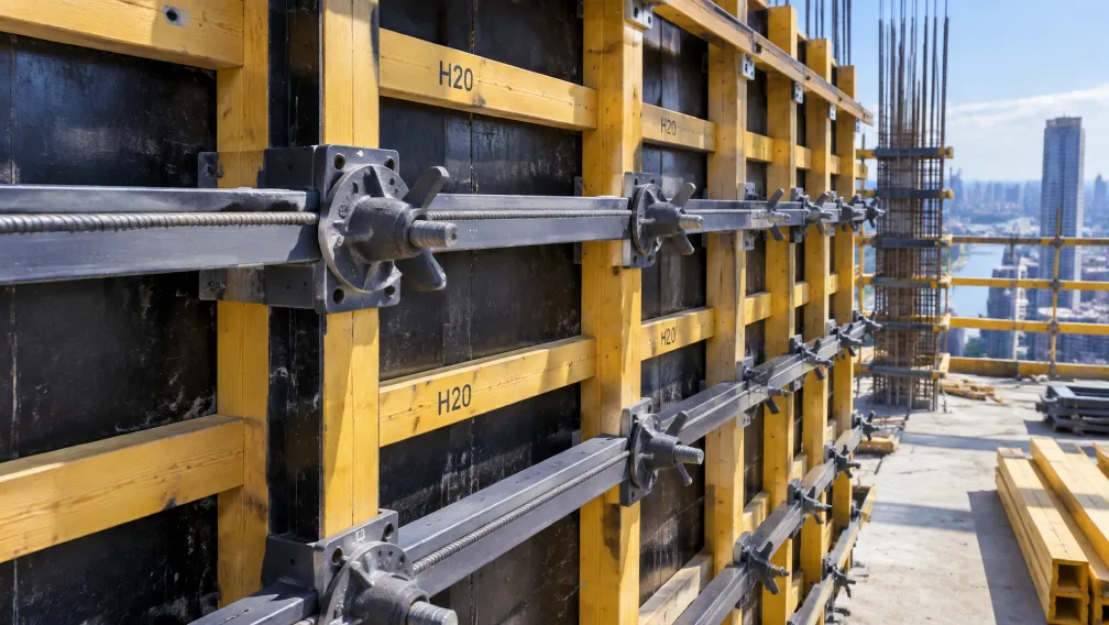
If the formwork panels are insufficiently restrained, the outward pressure causes them to bow, deform, or violently burst open—a catastrophic event known in civil engineering as a formwork blowout. To prevent this, site engineers deploy a continuous structural matrix that pins the opposing formwork panels together. This matrix consists of high-tensile steel rods passing directly through the liquid concrete, anchored on the exterior faces of the formwork by heavy-duty timber or steel wales, and locked into place using a scaffold wing nut. The physical and metallurgical integrity of this specific nut dictates the safety of the entire concrete pouring operation.
Direct Answer: What is a scaffold wing nut?
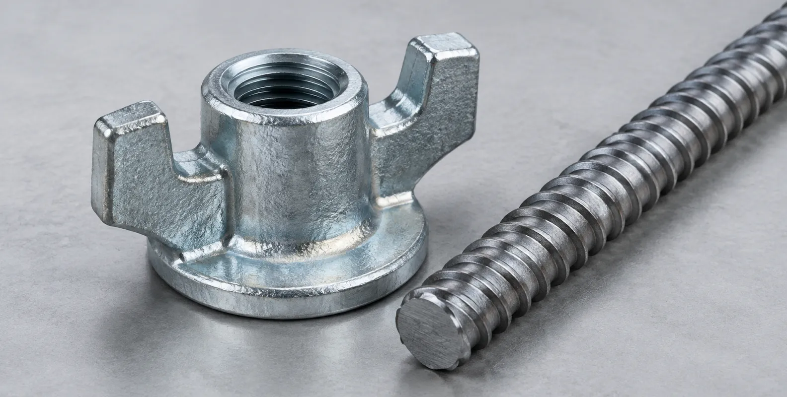
A scaffold wing nut is a heavy-duty, cast iron threaded fastener designed specifically to anchor formwork tie rods against the exterior bracing (wales) of concrete formwork panels. It features an enlarged circular base flange to distribute extreme clamping loads over a wide surface area and two or three prominent protruding "wings" (ears). These wings allow site workers to rapidly spin the nut down the coarse thread of a tie rod by hand and secure it permanently using direct sledgehammer strikes. Manufactured primarily from ductile iron (nodular cast iron), the wing nut resists extreme compressive forces and kinetic impact shocks without shattering, forming the primary tension-holding node in wall and column formwork systems.
Hydrostatic load calculations and tie-rod grid spacing
The placement and quantity of wing nuts and tie rods on a formwork panel are strictly governed by hydrostatic load calculations. Engineers reference standards such as DIN 18218 to determine the maximum fresh concrete pressure acting on the formwork face. The pressure depends heavily on the vibration methods used; internal poker vibrators liquefy the concrete, temporarily forcing it to behave as a true fluid, maximizing the outward thrust.
Once the peak lateral pressure is calculated in kiloNewtons per square meter (kN/m²), the engineer determines the grid spacing of the tie rods. If the maximum lateral pressure is 60 kN/m² and the tie rods are spaced in a 1.0m by 1.0m grid, each individual tie rod and its corresponding wing nut must constantly hold 60 kN of axial tension until the concrete sets. Procurement teams must match the Safe Working Load (SWL) of the wing nut to this specific tributary area load, adding mandatory safety factors to account for accidental dynamic shocks during the pour.
The D15/17 coarse thread: Defeating concrete fouling
A standard metric thread (e.g., M16 or M20) utilizes a fine thread pitch with sharp V-shaped valleys. Utilizing standard metric threaded rods and nuts in concrete construction guarantees failure. Liquid cement paste inevitably splatters onto the exposed threads extending past the formwork. When this paste hardens inside the microscopic valleys of a metric thread, the nut jams permanently. Workers cannot remove the formwork without cutting the rods with an oxy-acetylene torch.
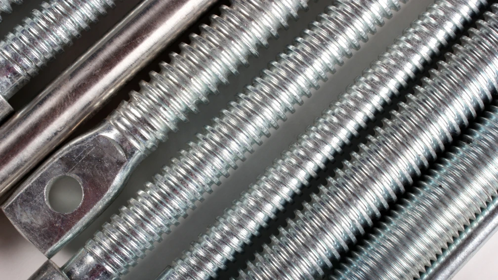
Formwork systems mandate the use of a specialized coarse thread, universally recognized as the D15/17 or Dywidag thread. The scaffold tie rod features an outer diameter of 17mm and a core diameter of 15mm, with a massive thread pitch of 10mm. The threads are rounded and extremely wide. This geometry is specifically engineered to be self-cleaning. When concrete hardens on a D15/17 rod, the sheer mechanical force of spinning the wing nut acts as an auger, breaking the brittle concrete and clearing the threads instantly. This guarantees that the formwork can be stripped rapidly and the hardware reused without specialized cleaning protocols.
Metallurgy of the wing nut: Ductile iron versus grey cast iron
Because site workers tighten and loosen wing nuts using direct strikes from heavy steel hammers, the metallurgical composition of the casting represents the most critical safety variable. Budget suppliers frequently cast wing nuts from Grey Cast Iron (such as HT200). Grey cast iron contains carbon in the form of graphite flakes. These microscopic flakes act as internal stress risers. Under a sudden kinetic shock—like a sledgehammer blow or a sudden pressure spike from a concrete pump—the grey iron fractures, and the wing nut shatters into pieces, instantly releasing the formwork.
Professional formwork hardware relies exclusively on Ductile Iron (Nodular Cast Iron, typically grade QT450-10 or EN-GJS-450-10). During the casting process, the addition of magnesium forces the graphite to precipitate as microscopic spheres (nodules) rather than flakes. This nodular microstructure eliminates the internal stress risers, granting the iron incredible elasticity. A ductile iron wing nut possesses a tensile strength exceeding 450 MPa and an elongation rate of 10%. It will dent, stretch, and deform under extreme sledgehammer impacts, but it will never shatter, providing an absolute safety margin during heavy construction operations.
Cold-rolled tie rods: Increasing tensile yield strength
The tie rod connecting the two opposing wing nuts must endure pure axial tension without stretching. Standard mild steel rods (Q235B) possess a yield strength of 235 MPa, which is insufficient for the heavy hydrostatic loads of commercial formwork; under pressure, mild steel stretches, causing the formwork panels to bulge outward and creating dimensionally defective concrete walls.
Heavy-duty formwork systems specify tie rods manufactured from medium-carbon steel (such as 45# steel) or high-tensile alloy steel (such as 42CrMo). More importantly, the D15/17 thread profile must be cold-rolled rather than machine-cut. Heavy industrial dies press into the steel bar, displacing the metal to form the threads without removing any material. This cold-working process physically compresses the grain structure at the thread root, significantly increasing the localized surface hardness and pushing the ultimate tensile failure load of the rod well beyond 180 kN. Cutting the threads with a lathe slices through the metallic grain, creating inherent weak points that snap under tension.
Bearing stress mechanics and the necessity of oversized flanges
The wing nut must transfer the massive axial tension of the tie rod into the horizontal or vertical supporting beams (wales) resting against the exterior of the formwork panel. These wales are frequently manufactured from structural timber (such as H20 timber beams). This creates a severe bearing stress challenge.
If a small nut presses against timber with 90 kN of force, the localized pressure vastly exceeds the compressive strength perpendicular to the grain of the wood. The nut crushes the wood fibers, burying itself deep into the timber wale. This localized crushing slacks the tie rod, allowing the formwork to bulge. To dissipate this force, manufacturers cast wing nuts with massive integrated circular base flanges, typically ranging from 70mm to 120mm in diameter. The 100mm or 120mm flange exponentially increases the surface contact area, reducing the localized bearing stress strictly below the crushing threshold of the timber, ensuring the formwork geometry remains perfectly rigid throughout the pour.
Separate washer plates versus integrated flanged wing nuts
Procurement teams select between two distinct wing nut architectures: separate components or integrated units.
A traditional system utilizes a standard two-wing nut paired with a separate heavy-duty square or rectangular steel washer plate (typically 120mm x 120mm x 10mm thick). This setup provides a massive bearing area suitable for heavy twin-channel steel wales. However, it requires workers to handle two separate loose components, increasing erection time and the likelihood of dropping parts from high scaffolding platforms.
The modern engineering preference is the integrated flanged wing nut (often called a combi-nut). The wide circular base plate and the winged nut are cast as a single monolithic unit. This eliminates loose washers entirely, accelerating the formwork assembly process and guaranteeing that workers never accidentally secure a tie rod without the mandatory bearing plate.
Articulated (swivel) wing nuts for non-perpendicular formwork
In complex architectural designs involving battered retaining walls, curved tanks, or angled abutments, the tie rod rarely passes through the formwork panel at a perfect 90-degree orthogonal angle. If a standard flat-flanged wing nut is tightened against a timber wale at a 10-degree offset, only one edge of the rigid flange makes contact.
This induces severe eccentric loading. The entire 90 kN tension force concentrates on a single point of the flange, and the tie rod is forced to bend sharply exactly where it exits the nut. This bending stress will snap a high-tensile tie rod. To resolve this, site engineers deploy articulated (swivel) wing nuts. The threaded nut section is seated inside a dished outer flange via a heavy-duty ball-and-socket joint. This allows the threaded core to pivot up to 15 degrees in any direction, automatically aligning perfectly with the angle of the tie rod while the outer flange remains completely flush against the timber wale. This neutralizes all eccentric bending moments, transferring the load as pure, safe axial tension.
Ergonomics of installation: Two-wing vs. three-wing designs
The geometric layout of the wings (ears) extending from the central hub dictates the installation ergonomics. The two-wing design features two large, opposing ears. This provides a wide striking area for heavy sledgehammers, allowing workers to easily apply maximum terminal tightening torque by striking the ears violently. However, spinning a two-wing nut rapidly by hand is less ergonomically efficient.
The three-wing design features three equally spaced ears. This profile is engineered specifically for rapid manual installation. A worker can spin the nut down a long tie rod highly efficiently by slapping the closely spaced wings with the palm of a gloved hand. While the striking target for a hammer is smaller, the three-wing design generally offers a thicker central hub, making it highly resistant to thread deformation under extreme tension.
Managing dynamic shock loads from internal concrete vibrators
Static hydrostatic pressure represents only the baseline load on the wing nut. The actual peak stress occurs dynamically during the concrete consolidation phase. Site workers insert heavy mechanical poker vibrators directly into the wet concrete to eliminate trapped air pockets and ensure smooth surface finishes.
The high-frequency vibration temporarily transforms the thick concrete slurry into a true, frictionless liquid, causing the outward hydrostatic pressure to spike instantly to its absolute mathematical maximum. Furthermore, if the heavy vibrating head accidentally strikes the internal portion of the tie rod, it sends a violent kinetic shockwave directly down the steel shaft into the cast iron wing nut. The ductile iron metallurgy of the wing nut and the cold-rolled threads of the tie rod must absorb these sudden dynamic spikes—often 20% to 30% higher than the calculated static load—without shattering or stripping.
Single-sided formwork and blind-wall anchoring techniques
When pouring concrete directly against an existing rock face, a sheet pile wall, or deep in a subterranean excavation, workers only have access to one side of the formwork. They cannot push a tie rod completely through and secure a wing nut on the opposite side. This scenario requires specialized blind-side anchoring.
In these cases, heavy-duty concrete threaded inserts (or rock anchors) are embedded into the existing substrate or poured blinding concrete. Site workers thread the D15/17 tie rods directly into these embedded inserts. The formwork panels are then erected, and the exterior wales are secured using standard wing nuts. To maintain exact concrete wall thickness and prevent the formwork from collapsing inward before the pour, workers utilize a formwork installation bolt and internal plastic spacer cones. The entire outward hydrostatic pressure of the pour is transferred through the wing nut, down the tie rod, and resisted entirely by the pull-out capacity of the blind-side threaded insert.
Water-retaining structures and cast-in water barriers
Standard tie rod assemblies utilize a smooth PVC sleeve (conduit) surrounding the tie rod inside the concrete. After the concrete cures, the wing nuts are removed, and the tie rod is easily pulled out through the sleeve. The empty sleeve hole is then plugged with cementitious grout. However, for subterranean basements, elevator pits, and water treatment tanks, this continuous hole presents a fatal waterproofing defect. Capillary action will eventually draw groundwater entirely through the plugged hole, flooding the interior.
For water-retaining structures, the central section of the tie rod must be permanently cast into the concrete. A specialized water stop (a heavy steel disc) is welded to the midpoint of a short section of tie rod. This cast-in section connects to removable outer tie rods via threaded hex couplers. The solid steel water stop physically blocks the capillary path through the wall. Once the exterior wing nuts and outer tie rods are removed, the resulting shallow recesses on the concrete surface are patched, leaving a 100% waterproof concrete core.
Thread galling and the necessity of anti-seize lubrication
When a cast iron wing nut rotates down a high-tensile steel tie rod under extreme clamping pressure, immense friction is generated between the thread flanks. If the threads are dry or contaminated with fine silica dust, this friction causes localized overheating, leading to thread galling (cold-welding).
Galling causes the microscopic high points of the two metals to physically fuse together. As the worker forces the nut further, the fused metal tears, completely destroying the thread profile and seizing the nut permanently onto the rod. To prevent this, formwork crews must implement strict lubrication protocols. Spraying the tie rods with extreme-pressure (EP) lubricants, specialized formwork release oils, or graphite-based anti-seize compounds before threading the wing nuts drastically reduces friction, ensures accurate torque application, and guarantees the components can be dismantled rapidly without requiring destructive cutting tools.
Surface treatments: Electro-galvanizing vs. natural black finish
Formwork hardware is subjected to the most abrasive and chemically aggressive environments in the construction sector. It operates continuously in highly alkaline cement slurry, abrasive sand, and torrential weather.
Many budget wing nuts are supplied in a "natural black" finish—essentially raw cast iron coated in a thin layer of protective transport oil. This oil wears off during the first use, and the casting begins to rust immediately. Heavy rust scales inside the coarse internal threads, making the nut difficult to spin by hand and slowing down erection times. Professional B2B procurement dictates that all wing nuts must undergo Electro-Galvanizing (Zinc Plating). While the zinc layer will eventually wear off the outer striking wings due to hammer impacts, the zinc plating inside the protected threads remains intact, providing long-term rust prevention and ensuring the nuts run smoothly up and down the tie rods across multiple rental cycles.
Identifying critical failure modes on the jobsite
Formwork components are reusable capital assets, but they degrade over time. Site safety officers and yard maintenance crews must execute strict visual inspections before redeploying wing nuts and tie rods to an active pour.
The primary failure mode for wing nuts is thread degradation. Inspectors examine the internal cast threads; if the crests of the threads are flattened, chipped, or overly wide, the nut will slip under hydrostatic pressure and must be scrapped. The secondary failure mode involves the wings. If a wing is visibly bent or cracked due to excessive sledgehammer abuse, the structural integrity of the casting is compromised. For tie rods, inspectors roll the rods on a flat steel table; any rod exhibiting a permanent bend cannot be reused, as straightening it cold induces metal fatigue and compromises its tensile capacity.
B2B procurement fraud: Detecting grey iron substitutions
The most pervasive and dangerous fraud in the international formwork hardware trade involves substituting cheap Grey Cast Iron for mandated Ductile Iron (Nodular Iron). Visually, a grey iron wing nut and a ductile iron wing nut look identical after galvanizing. However, grey iron costs significantly less to cast and is lethally brittle under impact.
If a supplier delivers grey iron wing nuts, the first hammer strike by an erection worker will shatter the ear off the nut. If the nut survives installation, the dynamic shock from a concrete vibrator can cause it to explode under tension, unleashing a massive formwork blowout. B2B buyers detect this fraud through strict metallurgical verification. Contracts must require official Mill Test Certificates (MTC) showing the specific nodular graphite microstructure, and independent laboratory Charpy impact test results proving the casting absorbs kinetic shock without shattering.
Destructive laboratory testing: Pull-to-failure limits
Verifying the mathematical limits of a wing nut and tie rod assembly requires brutal, independent laboratory testing. The assembly must not yield below its stated Safe Working Load (SWL), and it must provide an ultimate failure load that exceeds regional safety factors (typically 2.0 to 1).
In a laboratory pull-to-failure test, a section of tie rod is threaded with two opposing wing nuts and mounted in a high-capacity Universal Testing Machine (UTM). A hydraulic ram pulls the nuts apart, logging the force in kiloNewtons (kN). The engineers document exactly where the failure occurs. In a high-quality system, the cast iron wing nut should never crack, and its internal threads should never strip; the ultimate failure should only occur when the steel tie rod itself undergoes ductile elongation and eventually snaps (typically between 140 kN and 190 kN for a 15/17mm rod). If the cast iron threads strip out before the steel rod snaps, the wing nut metallurgy or thread tolerance is fundamentally defective.
Estimating hardware volumes for wall formwork logistics
Logistics planners calculate hardware requirements using precise grid arithmetic based on the specific formwork panel system and the concrete pour height. Every tie rod requires two wing nuts.
If pouring a standard 3.0-meter high retaining wall using large-panel timber formwork, the structural engineer may specify a tie rod grid of 1.0 meter horizontally and 1.0 meter vertically. A 50-meter long wall section would require roughly 50 tie rods per vertical meter. For a 3.0m height, this equals 150 tie rod assemblies. Therefore, this specific pour requires 150 lengths of tie rod, 300 wing nuts, 300 PVC sleeve tubes, and 600 plastic spacer cones. Procurement officers automatically apply a 5% to 10% attrition margin to the final wing nut order, as these components are frequently buried in mud, lost in deep excavations, or stolen during demobilization.
Connect with our engineering team for certified formwork hardware
Lengge Steel manufactures certified, heavy-duty formwork tie systems for the global civil engineering market. Our production lines supply fully traceable cold-rolled D15/17 tie rods, drop-forged water barriers, and precision-cast QT450-10 ductile iron wing nuts. We strictly guarantee our metallurgy against brittle shattering under hammer impact and enforce precise coarse-thread tolerances for rapid, jam-free installation. Submit your formwork system specifications, hydrostatic pressure limits, and bulk volume requirements to our engineering desk to receive a comprehensive structural quotation and certified third-party laboratory test documentation. Visit our contact page to secure your high-performance concrete forming supply chain today.
Frequently Asked Questions
If a wall formwork is subjected to a hydrostatic pressure of 60 kN/m², and the tie rods are spaced at 0.8m horizontally and 1.0m vertically, what is the axial tension on the wing nut?
The axial tension is calculated by determining the tributary area supported by a single tie rod and multiplying it by the hydrostatic pressure. The tributary area is $0.8 \text{ m} \times 1.0 \text{ m} = 0.8 \text{ m}^2$. The total force ($F$) equals the pressure ($P$) multiplied by the Area ($A$). Thus, $F = 60 \text{ kN/m}^2 \times 0.8 \text{ m}^2 = 48 \text{ kN}$. Therefore, the wing nut must safely hold a continuous axial tension of 48 kN throughout the concrete pour, requiring a component with a Safe Working Load (SWL) of at least 90 kN to provide an adequate safety margin for dynamic vibrator shocks.
Why are standard metric threaded rods (like M16 or M20) strictly prohibited for concrete formwork?
Standard metric threads feature fine pitches and sharp, narrow V-shaped valleys. In a concrete pouring environment, liquid cement paste inevitably splatters onto the exposed threads. When this highly alkaline paste hardens inside the narrow valleys of a metric thread, the nut jams permanently and cannot be unscrewed. The specialized D15/17 (Dywidag) thread utilizes an extremely wide, rounded 10mm pitch. This coarse geometry is self-cleaning; rotating the wing nut physically breaks and ejects the hardened concrete, ensuring rapid dismantling and component reuse.
What is the metallurgical difference between a ductile iron wing nut and a grey cast iron wing nut?
Grey cast iron contains carbon in the form of microscopic graphite flakes, which act as internal stress risers, making the metal highly brittle and prone to shattering under impact. Ductile iron (Nodular Cast Iron, QT450-10) contains magnesium additions that force the graphite to form microscopic spheres (nodules) instead of flakes. This nodular structure eliminates the stress risers, granting the metal immense elasticity and high tensile strength (450 MPa). A ductile iron wing nut absorbs sledgehammer strikes and kinetic shock loads by denting or stretching, whereas a grey iron nut explodes into fragments.
Why is an articulated (swivel) wing nut required when formwork walls are battered or angled?
When a tie rod passes through angled formwork, it does not exit the timber wale at a perfect 90-degree angle. If a standard flat wing nut is tightened against this angled timber, only one edge of the flange makes contact, inducing severe eccentric loading. The entire 90 kN tension concentrates on a single point, bending the tie rod sharply against the nut threads and snapping it. An articulated wing nut features a ball-and-socket joint that allows the threaded core to pivot up to 15 degrees, aligning perfectly with the tie rod while the outer flange remains completely flush against the wood, transferring the load as pure axial tension.
If a tie rod exerts 90 kN of tension, what is the bearing stress of a 100mm flanged wing nut pressing against a timber wale?
To calculate the bearing stress, first find the area of the 100mm circular flange. Area ($A$) = $\pi \times r^2 = 3.1415 \times (50\text{mm})^2 = 7853.7 \text{ mm}^2$. The bearing stress ($\sigma$) is Force divided by Area. $\sigma = 90,000 \text{ N} / 7853.7 \text{ mm}^2 = 11.46 \text{ MPa}$. Because the compressive strength perpendicular to the grain for standard softwood timber is typically only 3.0 to 7.0 MPa, a stress of 11.46 MPa will crush the wood fibers and sink the nut into the timber. This mathematical reality dictates why engineers must specify oversized 120mm flanged wing nuts or utilize heavy steel distribution washers to lower the bearing stress below the timber's crushing limit.
Why are cold-rolled tie rods structurally superior to machine-cut tie rods?
Machine-cutting a thread utilizes a lathe to slice away steel, physically reducing the cross-sectional area and severing the continuous metallic grain structure, creating inherent weak points at the root of every thread. Cold-rolling uses extreme hydraulic pressure to press dies into the steel bar, displacing the metal to form the thread profile without removing material. This cold-working process compresses the grain structure, increasing the localized surface hardness and pushing the ultimate tensile yield strength of the rod significantly higher than a cut thread counterpart.
How do contractors prevent capillary water leaks through tie rod holes in subterranean basements?
In standard formwork, tie rods are removed from a PVC sleeve, leaving a continuous hole through the concrete that groundwater can easily penetrate. For water-retaining structures, a solid steel water barrier (a wide steel disc) is factory-welded to the exact center of a short cast-in tie rod section. This central rod is left permanently embedded in the concrete. The steel disc physically blocks the capillary pathway through the wall, guaranteeing absolute waterproofing once the exterior removable tie rods are unthreaded and the surface recesses are patched.
What occurs during thread galling on a formwork tie rod, and how is it prevented?
Thread galling (cold-welding) happens when extreme friction and heat are generated by rotating threaded surfaces under massive clamping tension. The microscopic high points of the steel physically fuse together. As the worker forces the nut, the fused metal tears, destroying the thread profile and permanently seizing the wing nut onto the rod. Site crews prevent this by applying extreme-pressure (EP) lubricants, formwork release oils, or graphite-based anti-seize compounds to the tie rods prior to installation, creating a lubricating barrier against metal-to-metal fusion.
Why shouldn't a worker use a pneumatic impact wrench to tighten a scaffold wing nut?
Pneumatic impact wrenches lack precise torque control and can easily deliver over 150 Nm of torque instantly. Applying this extreme rotational force to a wing nut generates massive localized bearing stress, instantly crushing the cellular structure of the timber wales or deforming the hollow steel backing channels. Furthermore, the violent impact mechanism batters the cast iron wings, risking micro-fractures. Wing nuts must be tightened manually using the mechanical leverage of the wings or gentle strikes from a standard formwork hammer.
What documentation must a procurement manager demand to verify wing nut quality?
To prevent the deadly substitution of brittle grey cast iron, B2B buyers must demand official Mill Test Certificates (MTC) proving the chemical composition matches Ductile Iron (Nodular Iron QT450-10), specifically verifying the magnesium content required for nodularization. Furthermore, the supplier must provide independent laboratory pull-to-failure test reports demonstrating that the specific wing nut model safely holds an ultimate tensile load (typically exceeding 140 kN to 180 kN) without thread stripping or casting fracture.
-

Lengge
Cantilever Scaffolding System Manufacturer
Lengge is a China-based factory producing cantilever I-beams, tie rods, couplers, embedded parts and full scaffolding accessories. We supply contractors, wholesalers and rental companies in over 50 countries from our own production facility in Hebei.