LANGUAGE


The fundamental vulnerability of tension nodes in scaffolding
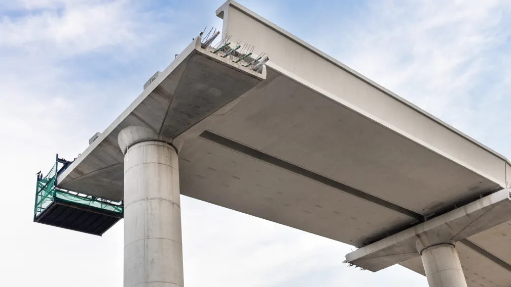
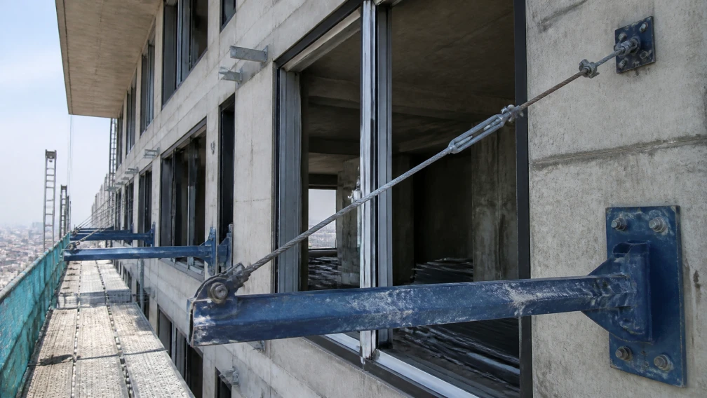
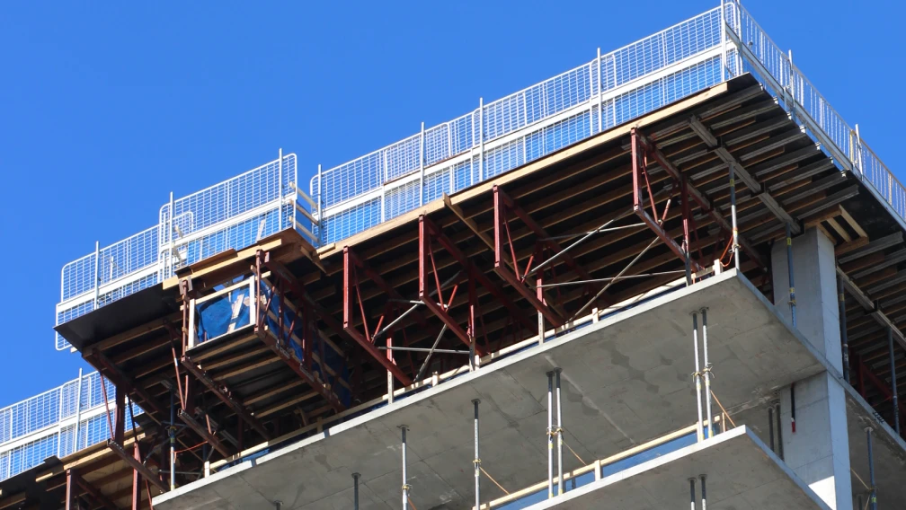
Cantilever scaffolding systems project massive staging platforms into open airspace, relying entirely on a complex matrix of compressive base beams and diagonal tension rods to counteract gravity. The load path travels from the timber decking, through the tubular standards, into the horizontal outrigger beams, and finally splits. A portion of the force drives horizontally into the concrete slab as compression, while the immense rotational bending moment transfers diagonally upward into the building’s core via high-tensile steel tie-rods.
The exact physical intersection where the horizontal steel beam transfers this extreme force into the diagonal tie-rod represents the single most vulnerable mechanical node in the entire staging structure. If this anchoring joint fails, the diagonal tension line severs, and the outrigger beam deflects past its ultimate yield point, triggering a catastrophic platform collapse. Modern structural engineering resolves this exact transfer of force by eliminating rigid, fixed-angle bolts and deploying a pivoting, high-capacity mechanical hinge known as the twin-ear anchor and clevis pin assembly.
Direct Answer: What is a twin-ear anchor and clevis pin assembly?
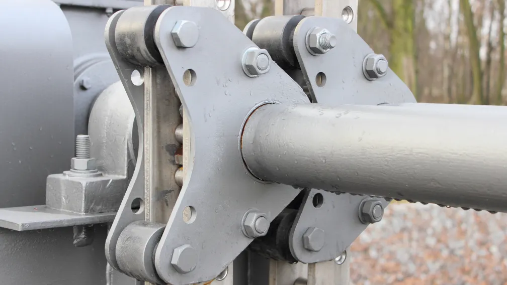
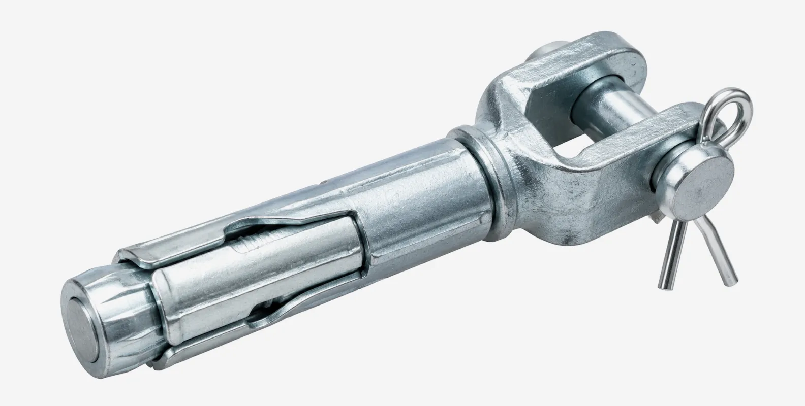
A twin-ear anchor is a heavy-duty, U-shaped structural steel bracket welded to a cantilever beam or cast into a concrete wall. It features two parallel vertical plates (ears) with precisely aligned holes. A clevis pin is a solid, unthreaded cylindrical steel fastener that passes horizontally through both ears. In cantilever scaffolding, the circular eyelet of a diagonal tie-rod sits exactly between the two ears, and the clevis pin locks it in place. This specific geometry creates a pivoting mechanical hinge that transfers massive structural loads through double shear, completely eliminating eccentric bending stress on the fastener while allowing the tie-rod to operate at any required diagonal angle.
The mechanics of eccentric loading and single-plate failures
To understand the engineering justification for the twin-ear design, site managers must analyze the failure mechanics of its predecessor: the single-plate lug. Historically, contractors welded a single flat steel plate with a hole to the outrigger beam, placed the tie-rod eyelet against it, and passed a heavy bolt through both.
This single-plate configuration introduces a deadly flaw known as eccentric loading. Because the tie-rod eyelet sits on one side of the plate, the line of force is physically offset from the center of the bolt. When tension is applied, the force pulls asymmetrically, creating a massive bending moment on the bolt shaft. The bolt is subjected simultaneously to lateral shear and extreme bending stress, causing the steel fibers on the outer curve of the bolt to stretch and yield. The bolt head digs into the plate, the shaft deforms, and the fastener eventually snaps under cyclic dynamic loading. Single-plate lugs are strictly prohibited in modern high-load cantilever tension lines.
The geometric advantage of the double shear plane
The twin-ear anchor neutralizes eccentric loading through symmetrical geometry. By placing the tie-rod eyelet exactly in the dead center of the two parallel ears, the line of tension perfectly aligns with the mechanical center of the anchor.
When upward diagonal force pulls on the tie-rod, the eyelet pulls against the middle of the clevis pin. The pin is supported on both the left and right sides by the steel ears of the anchor. This configuration forces the pin to resist the pulling force across two distinct cross-sectional planes simultaneously. In structural engineering, this is defined as a "double shear" connection. The mathematical shear capacity of the pin is effectively doubled compared to a single-plate connection, as the physical force required to sever the pin must simultaneously slice through two separate cross-sections of the steel cylinder.
Clevis pin metallurgy and shear stress limits
Because the entire load path converges on the physical cross-section of the pin, the metallurgical properties of the clevis pin dictate the ultimate safety margin of the cantilever node. Budget suppliers often machine pins from standard Q235B mild steel. While adequate for light-duty agricultural machinery, Q235B lacks the shear yield strength required for mega-tower cantilever supports.
Professional-grade clevis pins intended for heavy scaffolding nodes are machined from high-tensile carbon steel (such as Q355B) or specialized chromium alloy steel (such as 40Cr). The addition of chromium in the 40Cr alloy massively increases the hardenability and tensile strength of the steel matrix. After CNC machining, these premium pins undergo specialized heat treatment (quenching and tempering) to achieve a highly specific balance: the exterior surface becomes extremely hard to resist abrasive wear as the tie-rod pivots, while the inner core remains ductile to absorb sudden kinetic shock loads without brittle shattering.
The critical role of the flat washer in force distribution
A clevis pin features a solid, enlarged head on one end and a small cross-hole drilled near the opposite end to accept a retaining clip. When the pin is inserted through the twin-ear anchor, the small cross-hole protrudes past the second ear. Securing this pin requires a retaining clip, but deploying the clip directly against the steel ear introduces a localized wear hazard.
Site engineers must insert a heavy-duty flat washer over the pin before inserting the retaining clip. The washer serves a critical mechanical function. As the cantilever scaffolding vibrates under wind loads and worker traffic, the tie-rod transfers micro-vibrations into the pin, causing it to slide laterally back and forth by fractions of a millimeter. Without a flat washer, the thin wire of the retaining clip grinds directly against the rough edge of the anchor hole, quickly wearing through the wire and causing the pin to fall out. The flat washer distributes this lateral bearing force over a wide, smooth surface area, permanently protecting the structural integrity of the retaining clip.
Securing the clevis pin: Cotter pins vs. R-clips
The safety of the double shear connection relies on the clevis pin remaining fully engaged through both ears. If the pin slips out, the diagonal tie-rod detaches instantly. Two primary fasteners are utilized to lock the pin in place: split cotter pins and R-clips (bridge pins).
Split cotter pins provide a permanent, tamper-proof lock. The worker inserts the dual-pronged pin through the cross-hole and manually bends both prongs backward around the clevis pin shaft. This connection cannot vibrate loose, but it renders the cotter pin single-use; bending it back straight during dismantling causes the metal to fatigue and snap. For scaffolding fleets requiring rapid assembly and dismantling, engineers specify heavy-duty R-clips. Made from spring steel, the R-clip snaps securely over the outside of the pin shaft and can be removed and reused hundreds of times. However, R-clips must be sized perfectly to the pin diameter to ensure high-wind vibrations do not shake them loose.
Why standard threaded bolts cannot replace clevis pins
A widespread and deadly violation on disorganized construction sites involves workers losing the designated clevis pin and substituting a standard high-tensile hex bolt (e.g., an M20 Grade 8.8 bolt) through the twin-ear anchor to secure the tie-rod.
While an M20 Grade 8.8 bolt possesses immense tensile strength, it is engineered to stretch along its axis, not to act as a pivoting shear pin. The threads on the bolt shaft present massive mechanical deficits in a double-shear application. First, the cut threads physically reduce the cross-sectional area of the steel cylinder, lowering the total shear capacity. Second, the sharp V-shaped valleys of the threads act as severe stress risers; under dynamic shear loading, micro-cracks originate exactly at the root of these threads and propagate rapidly through the shaft. Finally, as the tie-rod eyelet pivots under wind load, the hard threads act like a file, grinding away the inner circumference of the eyelet. A certified clevis pin features a perfectly smooth, unthreaded shank (grip length) that spans the entire distance between the two anchor ears, ensuring maximum shear area and zero abrasive damage.
Welding standards for attaching anchors to outrigger beams
The twin-ear anchor must transfer the massive diagonal pull of the tie-rod directly into the horizontal outrigger beam. The physical bond between the anchor bracket and the steel beam dictates the load capacity. The anchor is typically positioned near the outer tip of the cantilever I-beam, welded directly to the top flange.
This welding process is governed by strict structural codes, such as AWS D1.1. Standard practice requires continuous fillet welds along both sides of the anchor base plates, typically sized at 8mm or 10mm depending on the flange thickness. Because the outrigger beams (usually Q355B steel) and the anchor plates are thick components, rapid welding causes localized rapid cooling, creating a brittle Heat Affected Zone (HAZ) prone to hydrogen embrittlement. Certified manufacturing facilities utilize strict pre-heating protocols before laying the weld, and employ robotic welding arms to ensure flawless, continuous bead penetration without the start-stop defects inherent in manual field welding.
Concrete embedment strategies for the upper anchor node
While the lower twin-ear anchor welds to the steel beam, the upper end of the diagonal tie-rod must anchor into the building's permanent concrete core. This upper node experiences the exact same tension forces and requires a corresponding twin-ear bracket to maintain the double-shear hinge effect.
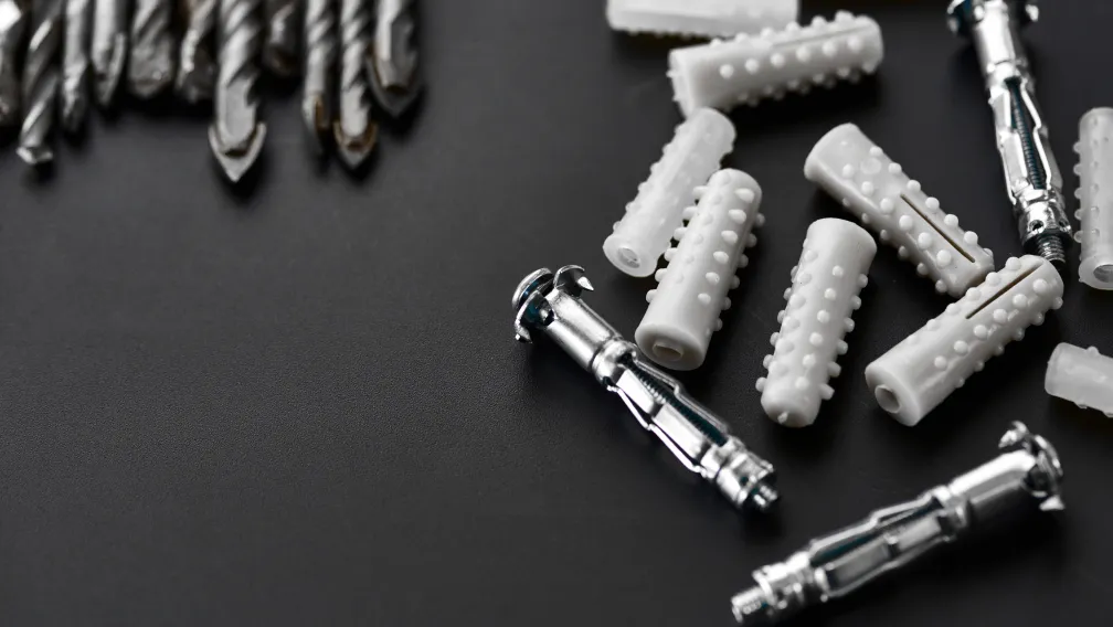
Site engineers deploy two primary methods for this upper connection. The most secure method involves casting a heavy steel plate directly into the concrete shear wall or edge beam during the initial pour, with the twin-ear lugs pre-welded to the exposed face. This utilizes the deep compressive mass of the concrete matrix to resist the pull-out force. In retrofit scenarios where casting is impossible, engineers use chemical anchoring. A heavy baseplate featuring the twin-ear lugs is bolted to the cured concrete wall using high-capacity epoxy chemical anchors. The chemical resin bonds the threaded anchor rods directly to the concrete pores, providing immense pull-out resistance that mechanical expansion anchors cannot match under cyclic dynamic loading.
Deflection mitigation through pivoting articulation
The primary architectural advantage of the twin-ear and clevis pin assembly is its rotational freedom. When a cantilever scaffolding system is erected, the specific geometry of the building dictates the exact angle of the diagonal tie-rod. Engineering codes mandate that this angle must remain between 45 and 60 degrees relative to the horizontal outrigger.
Because every building floor height differs slightly, the angle changes on every project. If the tie-rod were welded rigidly to the beam, forcing it to adapt to a new angle would bend the steel rod, inducing severe permanent stress before the platform is even loaded. The clevis pin acts as a mechanical hinge. The eyelet pivots freely around the smooth shank of the pin, automatically aligning the tie-rod to the exact geometric angle required by the building. This guarantees that 100% of the platform's load is transferred as pure axial tension along the rod, without any parasitic bending forces.
Integration with closed-body turnbuckles and tensioning
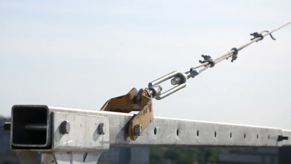
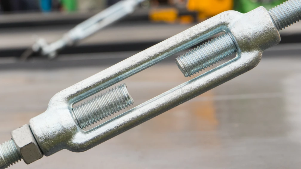
The tie-rod assembly requires precise length adjustment to effectively pre-tension the cantilever beam. This is achieved by integrating a closed-body turnbuckle into the middle of the tension line. The turnbuckle typically features a threaded jaw on one end and a threaded eyelet on the other.
The eyelet of the turnbuckle slots directly into the upper or lower twin-ear anchor and is locked by the clevis pin. Once both ends of the diagonal line are pinned securely in their respective anchors, site workers rotate the central steel body of the turnbuckle using a heavy wrench. The opposite internal threads draw the tie-rods inward simultaneously, pulling the outer tip of the cantilever beam slightly upward (cambering). This applied tension removes all slack from the clevis pin joints and pre-loads the outrigger beam to counteract the anticipated downward deflection of the scaffolding materials.
Pin tolerance and hole clearance: Preventing kinetic shock
The mathematical relationship between the outer diameter of the clevis pin and the inner diameter of the holes in the twin-ear anchor determines the dynamic stability of the node. This relationship is defined by machining tolerances.
If a supplier drills a 24mm hole in the anchor ears and supplies a 20mm clevis pin, the resulting 4mm clearance (slop) creates a deadly mechanical hazard. As wind shear strikes the scaffolding, the platform lifts and drops rapidly. During this micro-movement, the tension slackens and then engages violently. The 20mm pin slams against the 24mm hole wall, generating kinetic shock loads that massively exceed the static weight of the platform. This repeated hammering deforms the steel hole and can snap the pin. High-quality manufacturing mandates strict H7/g6 mechanical tolerances, ensuring the pin diameter matches the hole diameter with a clearance of less than 0.5mm, requiring a light hammer tap to insert. This tight fit entirely eliminates kinetic shock loading.
Bearing stress and the edge distance ratio
While double shear protects the clevis pin from snapping, the twin-ear anchor plates themselves face a different failure mode known as "tear-out" or bearing failure. As the pin is pulled diagonally upward by the tie-rod, it exerts immense localized pressure against the inner upper curve of the holes in the steel ears.
If the hole is drilled too close to the outer edge of the steel plate, this concentrated pressure will physically tear through the remaining steel, pulling the pin entirely out of the bracket. Structural engineering codes dictate a strict "edge distance ratio." The distance from the center of the drilled hole to the absolute edge of the steel plate must be at least 2.0 to 2.5 times the diameter of the clevis pin. Procurement officers verifying anchor dimensions must ensure the steel ears possess massive upper margins to resist this tear-out failure under extreme tension.
Destructive testing protocols for anchoring nodes
Verifying the mathematical limits of a twin-ear anchor requires brutal laboratory testing. Reputable manufacturers submit their fully welded cantilever beams and clevis assemblies to independent structural testing facilities before mass production.
The assembly is mounted in a high-capacity Universal Testing Machine (UTM). A hydraulic ram pulls diagonally against the clevis pin, simulating the exact load path of a tie-rod. The engineers monitor the force in kiloNewtons (kN) until the node suffers catastrophic failure. They document the exact failure mode: whether the clevis pin shears in half, the steel ears suffer tear-out, or the AWS D1.1 fillet welds rip away from the I-beam flange. The ultimate failure load is then divided by a standard safety factor (typically 2.0 to 4.0 depending on regional scaffolding codes) to establish the official Safe Working Load (SWL) stamped on the component.
Surface treatments: Defeating corrosion in pivoting joints
Cantilever outriggers and their tensioning hardware are exposed to the harshest atmospheric conditions on a construction site. Torrential rain, coastal salt-fog, and airborne cement dust constantly attack the raw steel. For rigid components, rust causes a gradual loss of wall thickness. For the twin-ear anchor, rust causes a fatal mechanical failure known as rust-lock.
If the clevis pin rusts inside the eyelet of the tie-rod or the anchor ears, the parts fuse together. The assembly loses its ability to pivot and articulate. When the scaffolding sways under wind load, the fused joint forces the rigid tie-rod to bend, inducing severe fatigue stress. To guarantee smooth pivoting across a multi-year project lifespan, the entire outrigger beam, twin-ear anchor, and clevis pin must undergo Hot-Dip Galvanizing (HDG). The 80-micron zinc-iron alloy coating provides total cathodic protection against oxidation, ensuring the hinge remains fully lubricated by the zinc layer regardless of environmental exposure.
The necessity of pre-fabrication over site welding
Attempting to manufacture a twin-ear tension node on an active jobsite introduces unmanageable risks. Site workers tasked with welding raw steel plates to the flange of an outrigger beam lack the specialized jigs required to keep the two ears perfectly parallel. If the ears are welded even two degrees out of parallel, the clevis pin will not pass through both holes.
Furthermore, manual field welding is highly susceptible to wind, moisture, and poor root penetration. Site managers rarely possess portable ultrasonic testing equipment to verify the internal integrity of a field weld. Modern procurement mandates 100% factory pre-fabrication. The supplier robotically welds the twin-ear anchors to the cantilever beams in a controlled environment, executes mandatory non-destructive testing (NDT), and galvanizes the entire assembly as a single monolithic unit. This eliminates hot-work on the high-rise floor and guarantees the anchor meets the certified Safe Working Load.
Managing high-cycle fatigue from wind shear
Cantilever scaffolding nodes do not experience smooth, continuous tension. The tie-rod tension fluctuates violently as wind shear strikes the solid debris netting covering the facade. A 30 kN baseline tension may spike to 45 kN and drop back to 30 kN repeatedly over a 24-hour storm cycle. This phenomenon is known as high-cycle fatigue.
Steel subjected to repeated stress fluctuations eventually develops microscopic surface cracks that propagate inward until the component snaps—often at loads far below its ultimate yield strength. The smooth, threadless shank of a certified clevis pin provides maximum resistance to fatigue cracking by eliminating the sharp surface valleys (stress risers) found on threaded bolts. Furthermore, utilizing highly ductile Q355B steel for the anchor ears ensures the plates can absorb micro-flexing without brittle shattering over the platform's operational lifespan.
Inspection protocols for the tie-rod anchor node
Site safety officers must execute rigorous weekly inspections of all cantilever tension nodes. The inspection begins by verifying that the retaining clips (split pins or R-clips) are present and properly seated against the flat washers on every single clevis pin.
Next, the inspector performs a visual audit of the anchor holes. The inspector looks for any signs of hole elongation. If the perfectly circular hole has stretched into an oval shape, it indicates that the localized bearing stress has exceeded the yield point of the steel plate, and tear-out failure is imminent. The inspector must also check the root of the fillet welds connecting the anchor to the outrigger beam for hairline cracks or flaking paint/zinc, which indicates the weld is yielding under tension. Any deformation requires the immediate evacuation of the staging platform above.
B2B procurement specifications for global compliance
Importing the critical nodes of a cantilever scaffolding system requires exhaustive supply chain verification. Procurement managers cannot risk the liability of counterfeit fasteners or low-grade steel failing on a high-profile mega-project.
To establish a secure supply chain, commercial buyers must mandate the following documentation in their purchase contracts:
- Mill Test Certificates (MTC): Demand official MTCs proving the clevis pins are machined from verified high-tensile alloys like 40Cr or Q355B, and rejecting any mild Q235B substitutions.
- Welding NDT Reports: Require third-party non-destructive testing reports (ultrasonic or radiographic) verifying full penetration and zero internal voiding on the factory welds connecting the twin-ear anchors to the beams.
- Tolerance Guarantees: Specify precise machining tolerances (e.g., H7/g6) for the pin and hole diameters to ensure zero kinetic slop in the pivoting joint.
- Destructive Test Data: The manufacturer must supply independent laboratory pull-test reports demonstrating the ultimate failure load of the completely assembled twin-ear and clevis pin node.
Estimating anchor and pin quantities for mega-projects
Logistics planners calculate hardware requirements based on the structural grid of the cantilever staging. Every single horizontal outrigger beam projecting from the building requires a diagonal tension line to manage deflection.
A standard tie-rod assembly requires two complete twin-ear nodes: one lower anchor welded to the beam, and one upper anchor embedded in the concrete wall. Therefore, every individual outrigger beam requires exactly two clevis pins, two flat washers, and two retaining clips. If a commercial facade requires 150 outrigger beams to encircle the perimeter, the logistics team must procure 300 twin-ear anchors (if purchasing the upper wall plates separately) and 300 complete clevis pin sets. Procurement officers automatically apply a 10% to 15% attrition margin specifically for the clevis pins, washers, and clips, as these small components are easily dropped down elevator shafts or lost in the mud during the chaotic erection phase.
Connect with our engineering team for certified tension nodes
Lengge Steel manufactures certified, heavy-duty cantilever scaffolding systems for global high-rise logistics. Our production lines supply fully prefabricated Q355B cantilever I-beams featuring robotically welded twin-ear anchors, complete with high-tensile 40Cr clevis pins, precision flat washers, and heavy-duty closed-body turnbuckles. We enforce strict H7/g6 machining tolerances and premium hot-dip galvanizing to ensure flawless pivoting articulation and massive shear capacity under extreme wind loads. Submit your project blueprints, target projection limits, and tension requirements to our engineering desk to receive a comprehensive structural quotation and certified laboratory test documentation. Visit our contact page to secure your high-performance facade access supply chain today.
Frequently Asked Questions
If a diagonal tie-rod carries 40 kN of tension, what is the shear force acting on the clevis pin in a twin-ear anchor?
The tie-rod eyelet sits precisely in the center of the twin-ear anchor, supported on both sides by the steel plates. This configuration forces the pin to resist the pulling load across two distinct cross-sectional planes simultaneously. Dividing the total 40 kN tension load by the two shear planes yields a localized shear force of exactly 20 kN acting upon each cross-section of the clevis pin. This double-shear geometry effectively cuts the mechanical stress on the fastener in half compared to a single-plate connection.
Why is a twin-ear anchor mechanically safer than a single-plate lug?
Bolting a tie-rod eyelet to a single flat plate places the load path off-center from the bolt. When tension is applied, this offset pulls asymmetrically, creating a severe eccentric bending moment that forces the bolt to bend while simultaneously subjected to shear. The twin-ear anchor encapsulates the eyelet in the dead center of the U-bracket, perfectly aligning the tension force with the mechanical center of the pin, neutralizing all eccentric bending stress and transferring the load as pure double-shear.
Why can't I replace a lost clevis pin with a standard Grade 8.8 threaded bolt?
A standard structural bolt is threaded along its shaft. The V-shaped valleys of cut threads physically reduce the cross-sectional area of the steel cylinder, lowering its total shear capacity. More dangerously, the sharp roots of the threads act as massive stress risers; under dynamic high-wind loading, microscopic fatigue cracks originate exactly in these thread valleys and propagate until the bolt snaps. A certified clevis pin utilizes a smooth, unthreaded shank to guarantee maximum cross-sectional area and eliminate stress risers across the shear planes.
What is the purpose of the flat washer in the clevis pin assembly?
The clevis pin is locked into the twin-ear anchor using a thin wire retaining clip (cotter pin or R-clip) inserted through a small cross-hole. As the scaffolding vibrates dynamically under worker traffic, the pin slides laterally by microscopic amounts. Without a washer, the thin retaining wire grinds violently against the hard, sharp edge of the steel ear hole, quickly wearing through the wire and causing the pin to fall out. The heavy-duty flat washer distributes this lateral bearing force over a wide, smooth area, protecting the retaining clip from abrasive destruction.
How do you determine if the hole in a twin-ear anchor is drilled too close to the edge?
Structural engineering codes dictate the edge distance ratio to prevent the pin from physically tearing through the steel plate under extreme tension. The mathematical distance from the absolute center of the drilled hole to the closest outer edge of the steel plate must equal a minimum of 2.0 to 2.5 times the diameter of the clevis pin. If a 20mm pin is used, the center of the hole must be at least 40mm to 50mm away from the edge of the plate to prevent catastrophic bearing failure (tear-out).
Why must twin-ear anchors be welded to the cantilever beams in a factory rather than on-site?
Site workers manually welding raw steel plates to thick outrigger beams lack the precision jigs required to keep the two ears perfectly parallel; a deviation of just two degrees prevents the clevis pin from passing through both holes. Furthermore, field welding thick Q355B steel in erratic weather causes rapid cooling, creating brittle Heat Affected Zones (HAZ), and site managers cannot easily perform ultrasonic non-destructive testing (NDT) to verify penetration. Factory pre-fabrication utilizes robotic welding, proper pre-heating, and mandatory NDT to guarantee the Safe Working Load.
How does hot-dip galvanizing affect the precise tolerances of the clevis pin and hole?
Hot-dip galvanizing applies a thick 60-to-80 micron layer of zinc to all steel surfaces. If a manufacturer drills a 20mm hole and machines a 19.8mm pin, the addition of the zinc coating will make the pin too thick to fit through the hole. Professional suppliers account for this by mathematically oversizing the holes in the twin-ear anchor by roughly 1.5mm to 2.0mm prior to galvanizing, ensuring that once the thick zinc-iron alloy layer is bonded, the final assembly maintains a tight, kinetic-shock-free clearance.
What physical evidence indicates that a twin-ear anchor is failing under overload?
The earliest visual indicator of impending failure is hole elongation. If the extreme localized bearing stress exerted by the clevis pin exceeds the yield point of the steel plate, the perfectly circular hole will stretch and deform into an oval shape. This plastic deformation proves the component has been subjected to forces far beyond its Safe Working Load, and the entire outrigger beam must be decommissioned immediately to prevent the pin from tearing entirely through the ear.
Why is the pivoting articulation of the clevis pin vital for tie-rod installation?
Because building floor heights vary, the exact diagonal angle of the tie-rod changes on every project, typically ranging between 45 and 60 degrees. If the tie-rod were rigidly welded or bolted tightly to a fixed plate, forcing it into a new angle would bend the steel rod, introducing severe permanent stress before the platform is even loaded. The clevis pin acts as a flawless mechanical hinge, allowing the eyelet to pivot freely and automatically align to the exact geometric angle required, guaranteeing the load transfers as pure axial tension.
What metallurgical documentation verifies the strength of the clevis pin?
B2B procurement managers must demand official Mill Test Certificates (MTC) from the foundry that produced the raw steel round bar. The MTC traces the specific heat batch and proves the chemical composition (carbon and chromium percentages) matches high-tensile alloys like 40Cr or Q355B. Furthermore, the supplier must provide independent laboratory destruction test reports verifying the actual shear failure threshold of the completed pin under a hydraulic testing machine.
-

Lengge
Cantilever Scaffolding System Manufacturer
Lengge is a China-based factory producing cantilever I-beams, tie rods, couplers, embedded parts and full scaffolding accessories. We supply contractors, wholesalers and rental companies in over 50 countries from our own production facility in Hebei.