LANGUAGE


The operational bottleneck of high-rise construction logistics
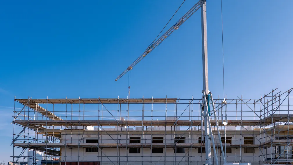
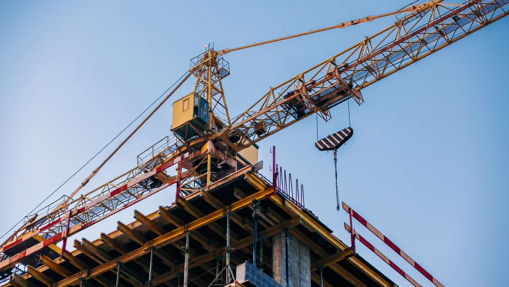
In high-rise commercial construction and mega-tower developments, vertical logistics represent the primary bottleneck governing the entire project schedule. Moving heavy palletized materials, scaffolding tubes, formwork panels, and concrete skips from the ground level to active working floors requires continuous tower crane operations. However, tower cranes cannot deposit materials directly into the interior of a building structure once the floor slabs above are poured and cured. Dropping materials solely on the uppermost exposed deck creates extreme congestion and forces laborers to manually carry heavy loads down internal stairwells or temporary hoists, severely reducing site productivity.
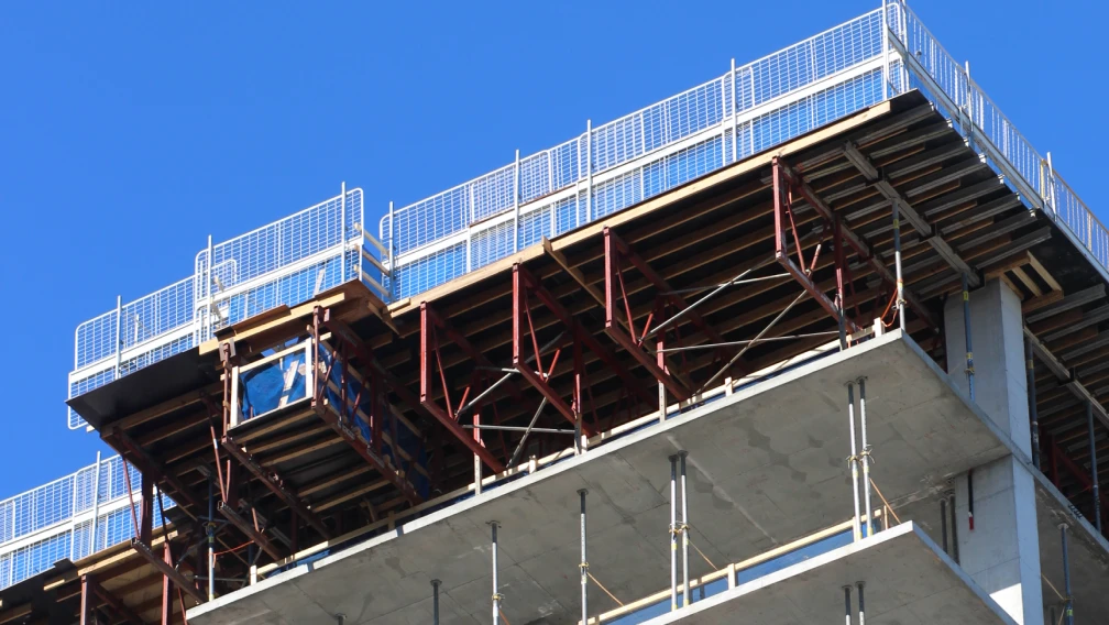
To resolve this logistics deficit, site engineers deploy heavy-duty temporary structures projecting outward from the building facade. These staging zones provide an open-air landing target for the crane hook at various intermediate floor levels. The primary structural component responsible for handling these extreme dynamic hoisting loads is the material loading platform (often referred to as an outrigger deck, crane loading deck, or retractable loading bay). The engineering tolerances, anchoring mechanisms, and deflection limits of these platforms dictate the safety and efficiency of the entire site's supply chain.
Direct Answer: What is a material loading platform?
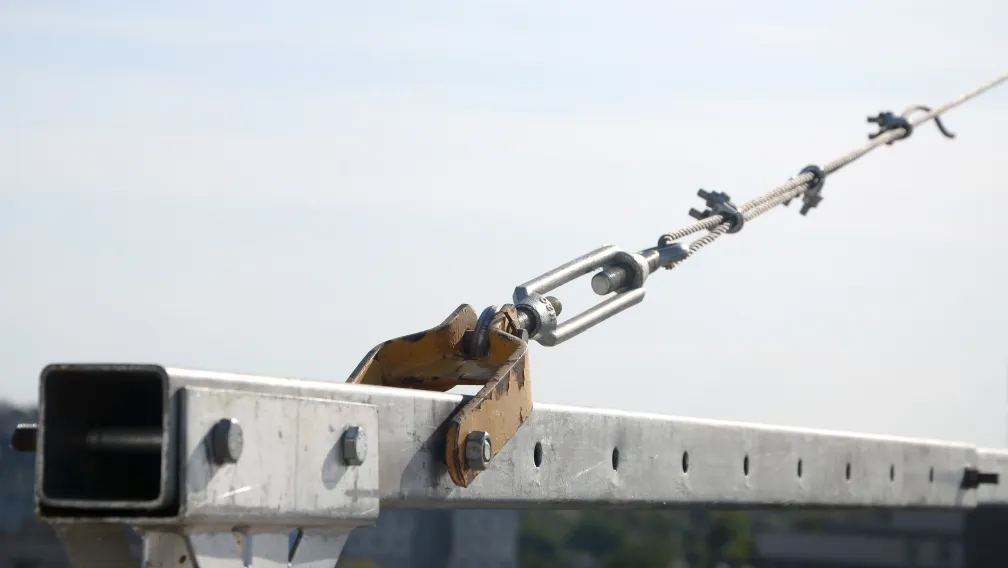
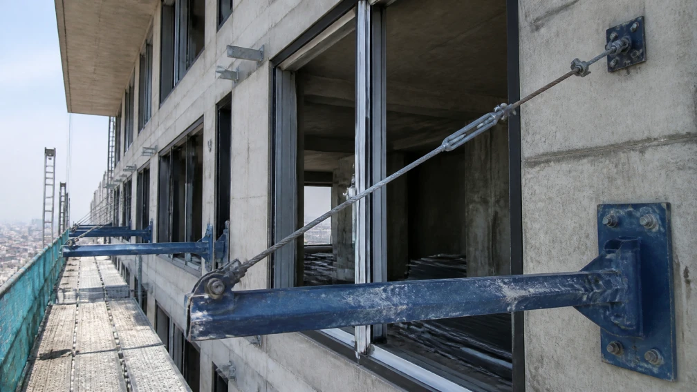
A material loading platform is a heavy-duty, temporary cantilevered steel structure anchored to a building's interior floor slab and projecting outward past the facade. It provides a highly visible, open-air staging area for tower cranes to land heavy construction materials directly onto active floors. Typically constructed from Q355B high-strength structural steel, these platforms handle safe working loads ranging from 2,500 kg to 5,000 kg. They utilize a combination of inboard counter-levering and heavy-duty adjustable steel props compressed against the ceiling slab to counteract the massive bending moments generated when heavy payloads are deposited on the outboard deck.
Primary structural framework and steel metallurgy
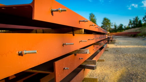
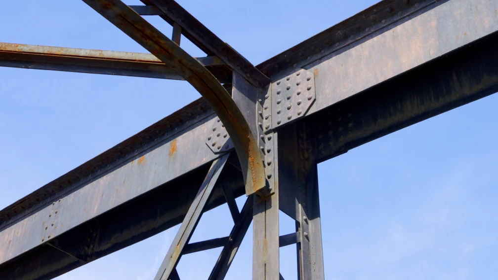
The structural skeleton of a material loading platform must endure brutal operational conditions. It faces continuous cyclic loading, accidental crane impacts, extreme weather exposure, and heavy point loads from forklift wheels or concentrated material pallets. A standard platform frame utilizes deep steel sections for the main longitudinal support beams. These main outriggers are frequently fabricated from 18# or 20# cantilever I-beams, or heavy H-section profiles, depending on the required outboard projection and target weight capacity.
Material selection is strictly regulated. Basic Q235B mild steel lacks the yield strength necessary to resist permanent plastic deformation under the bending moments created by a 5-ton load situated three meters outside the building edge. Professional equipment manufacturers fabricate the primary load-bearing members from Q355B (or equivalent S355JR / ASTM A572 Grade 50) low-alloy high-strength steel. This upgrade provides a minimum yield strength of 355 MPa, granting the structure the capacity to handle heavy dynamic forces without increasing the cross-sectional mass of the platform to unmanageable levels. Welding on these primary members must comply with strict AWS D1.1 structural welding codes, requiring full-penetration butt welds and mandatory non-destructive testing (NDT), such as ultrasonic or radiographic flaw detection, before the unit leaves the factory.
The physics of the cantilever span and the fulcrum effect
A material loading platform operates on basic mechanical lever principles. The edge of the concrete floor slab acts as the fulcrum. The platform is divided into two distinct sections: the outboard section (the deck projecting into the air) and the inboard section (the tail resting inside the building). When a crane places a load on the outboard deck, it generates a massive rotational force (bending moment) pivoting over the slab edge, attempting to rip the inboard tail upward.
To safely counteract this rotational force without over-stressing the anchor points, the structural geometry of the platform must adhere to a strict internal-to-external length ratio. Standard engineering practice requires an inboard tail length that is at least 1.5 times the length of the outboard projection. For example, if a loading deck projects 3.0 meters past the building facade, the inboard tail must extend at least 4.5 meters into the building. This geometry mechanically neutralizes a significant portion of the bending moment through simple leverage, transferring the residual uplift forces into the rear anchoring system.
Anchoring systems: Adjustable steel props and compressive thrust
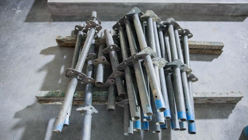
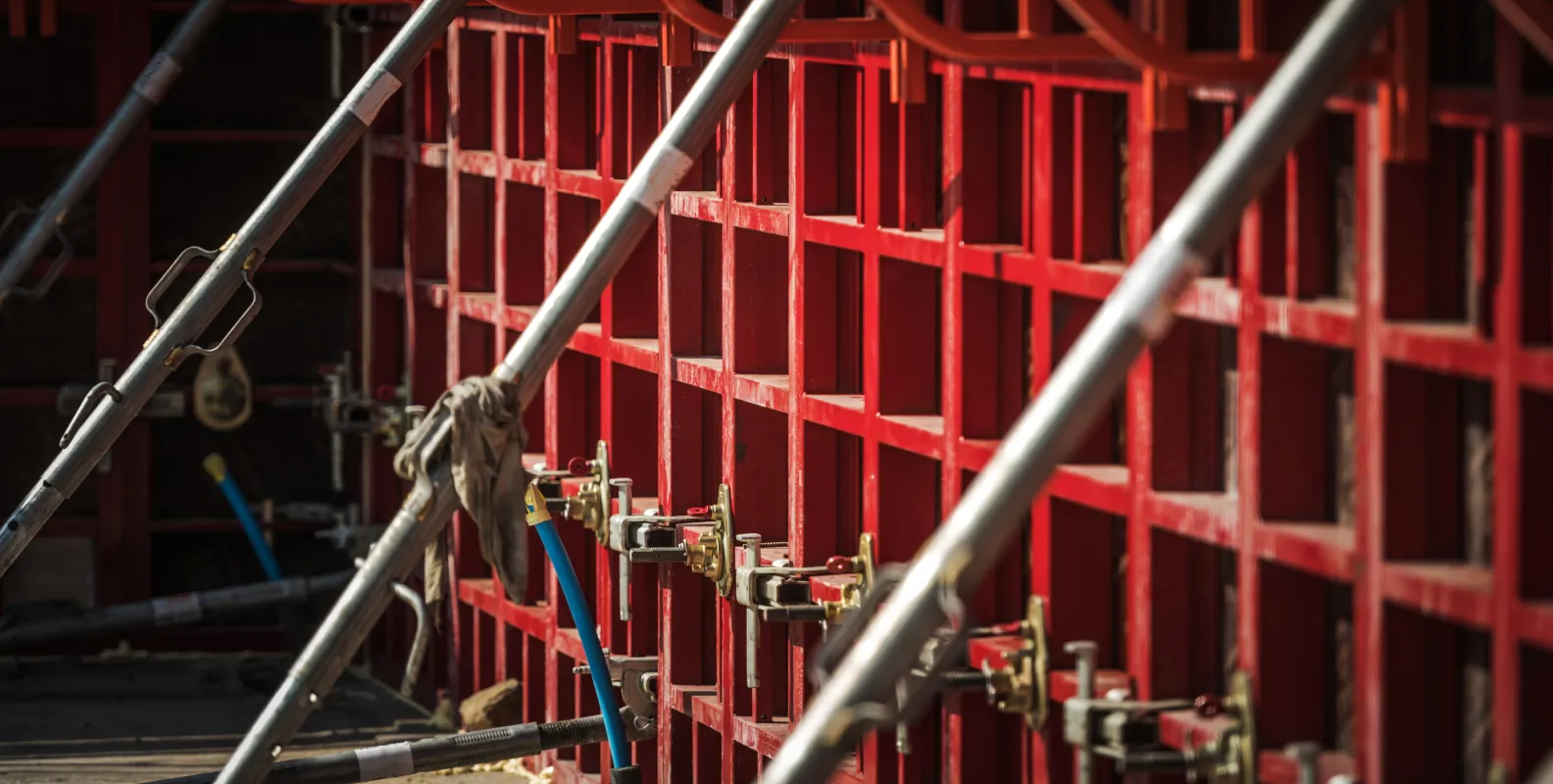
Securing the inboard tail of the platform requires massive vertical restraint. The most common and highly efficient anchoring method involves compressing the tail of the platform against the concrete ceiling slab of the floor above. This is achieved using heavy-duty adjustable steel props.
Typically, four to six heavy-duty steel props are positioned vertically along the inboard tail beams. Workers extend the inner tubes of the props upward until they contact the ceiling. By tightening the threaded collar nuts using specialized striking wrenches, the workers apply immense pre-tension, jacking the props tightly between the platform's steel beams and the concrete ceiling. When a load is applied to the outboard deck, the tail attempts to lift, instantly transferring that upward force as pure compression into the steel props, which push directly against the overhead slab.
The physical capacity of these props is the ultimate fail-point of the system. Light-duty props designed for basic formwork will buckle under the uplift forces of a fully loaded staging deck. Procurement specifications must mandate EN 1065 Class C or Class D heavy-duty props possessing a wall thickness of at least 3.0mm. Furthermore, the props must feature drop-forged collar nuts and high-tensile locking pins to prevent thread stripping or shear failure during a heavy crane landing.
Alternative anchoring: Through-slab bolting mechanisms
In certain architectural scenarios, such as the top floor of a building where no overhead concrete slab exists to brace against, adjustable steel props cannot be used. Site engineers must transition to a direct through-slab bolting method to secure the inboard tail.
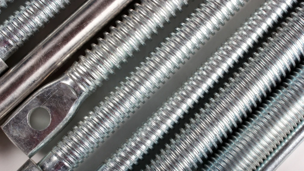
This involves drilling large-diameter holes entirely through the cured concrete floor slab. Heavy-duty threaded rods (typically M24 or M30 high-tensile steel) are passed through the platform's anchoring brackets, down through the concrete floor, and secured to massive steel spreader plates bolted against the underside of the slab. This configuration relies on the concrete's punching shear capacity and the tensile strength of the threaded rods to resist the uplift forces. While highly secure, this method requires destructive drilling, introduces potential water leakage points that require patching later, and demands access to the floor directly below, which may disrupt finishing trades.
Overcoming concrete curing timelines and slab punch-out forces
Regardless of whether the platform uses compressive steel props or through-slab bolts, the ultimate load is always transferred into the building's concrete structure. This creates a severe scheduling conflict in rapid high-rise construction: concrete requires time to cure before it can bear heavy mechanical loads.
Site engineers must consult the structural design calculations to determine when a loading platform can be safely installed on a newly poured floor. Standard protocol dictates that the concrete must reach a minimum of 75% of its 28-day design compressive strength before any prop tension or platform loads are introduced. Applying a 5-ton point load (transferred via the prop base plates) onto "green" (uncured) concrete will cause localized crushing or catastrophic punching shear failure, where the prop punches a hole directly through the ceiling slab.
The necessity of back-propping multiple floor levels
Even when the concrete has achieved full design strength, the concentrated loads generated by a loading platform often exceed the live-load rating of a single residential or commercial floor slab. An standard office slab is designed to support desks and people, not the concentrated uplift thrust of a 5-ton staging deck.
To prevent structural cracking of the building, site engineers implement a protocol known as "back-propping." Back-propping involves installing additional temporary adjustable steel props directly below the platform's footprint on the floors beneath. If the platform props push up against Floor 10, back-props are installed on Floor 9 directly underneath the contact points, transferring a percentage of the stress down to Floor 8. In heavy logistics scenarios, engineering blueprints may require two or even three levels of continuous back-propping to safely distribute the extreme localized forces across the broader building frame.
Static ratings versus dynamic crane impact factors
When reviewing the specifications of a material loading platform, buyers encounter the Safe Working Load (SWL). A platform rated for an SWL of 3,000 kg implies it can hold that weight statically. However, crane logistics are inherently dynamic. When a tower crane lowers a heavy pallet of masonry blocks onto the deck, the downward velocity, the sudden stopping of the winch, and the minor swinging of the load generate severe kinetic energy.
Structural engineers account for this by applying a Dynamic Impact Factor to all platform calculations. International lifting standards typically mandate a dynamic multiplier of 1.25 to 1.30. Therefore, a platform rated for a 3,000 kg SWL is actually engineered to withstand a momentary impact force equivalent to nearly 4,000 kg without yielding. Site safety officers must ensure that riggers do not drop loads abruptly. Even a platform built from heavy Q355B steel can suffer localized web buckling or deck plate deformation if a crane operator “free-falls” a load onto the structure.
Understanding uniformly distributed loads (UDL) versus point loads
Another critical aspect of deck overloading involves load distribution. A loading platform’s SWL is calculated based on a Uniformly Distributed Load (UDL), meaning the weight is spread evenly across the entire surface area of the outboard deck. Distributing the weight ensures that all the supporting longitudinal I-beams share the stress equally.
However, construction realities often violate UDL assumptions. Landing a heavy, compact generator or using a heavy motorized pallet jack places the entire mass onto four tiny contact points. This severe point loading can punch through the steel deck plate or permanently bend a single underlying support joist, even if the total weight is technically below the platform's maximum SWL. Operators must utilize heavy timber dunnage (spreader beams) to distribute the footprint of dense, heavy items across multiple structural joists before releasing the crane rigging.
Deck surface engineering: Chequer plate vs. heavy timber
The flooring material of the outboard deck must balance high friction for worker safety, extreme durability against dragging pallets, and overall weight control to maximize the platform's payload capacity.
Heavy Timber Decking: Many platforms utilize thick, treated hardwood planks (typically 50mm thick). Timber provides excellent natural friction, preventing materials from sliding in wet conditions. It absorbs minor crane impacts well by flexing slightly, protecting the underlying steel frame from shock. Furthermore, damaged planks are cheap and easy to replace on site without hot-work. However, timber rots over time, absorbs water (adding dead weight), and requires frequent inspection for splintering or cracking.
Steel Chequer Plate: Premium platforms feature fully welded steel chequer plate flooring (typically 4mm to 6mm thick with a raised diamond pattern). Steel provides permanent structural rigidity, zero water absorption, and a much longer rental lifespan without maintenance. However, it adds significant dead weight to the platform assembly and can become dangerously slippery when covered in mud or wet cement paste, requiring routine high-pressure washing by site laborers.
Retractable loading platform mechanics and locking systems
A major innovation in high-rise logistics is the retractable (or "drawer-style") material loading platform. Fixed platforms block the vertical crane path for any platforms located directly below them. A retractable unit solves this by featuring a moving outboard deck that rolls in and out of a fixed stationary base frame.
The base frame remains anchored inside the building. The moving deck runs on heavy-duty, sealed steel roller bearings integrated into the main channels. When the crane needs to drop materials to Floor 15, the workers manually push the outboard deck of Floor 15 outward. Once loaded and cleared, they pull the empty deck back inside the building, completely opening the vertical airspace for the crane to access Floor 14 directly below.
The safety of a retractable unit depends entirely on its locking mechanisms. When fully extended or fully retracted, the deck must be mechanically locked to prevent accidental movement due to wind or floor sloping. Site crews utilize heavy-duty scaffold positioning pins or heavy forged drop-pins that pass directly through aligned holes in the stationary frame and the moving deck beams. These pins must be secured with safety clips (R-clips) to guarantee the deck cannot roll unexpectedly while workers are retrieving materials.
Safety gate systems and fall protection engineering
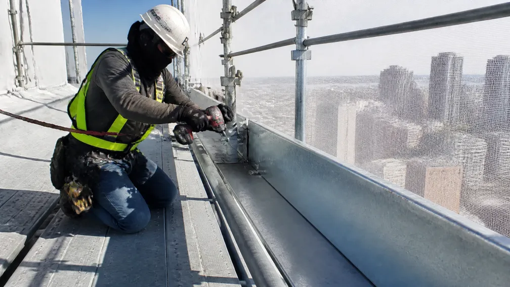
Working on an open-air platform thirty stories above the ground requires flawless fall protection integration. Every loading platform features structural safety barriers along the outboard perimeter, typically built to a minimum height of 1.2 meters, with integrated mid-rails and rigid steel toe-boards to prevent debris from being kicked over the edge.
The front access point presents a unique engineering challenge. The crane hook must access the deck, meaning the front barrier must open. Premium platforms utilize inward-swinging gates or removable steel chains. Inward-swinging gates are vastly superior; if a worker trips and falls against the gate, the mechanical stops prevent the gate from opening outward into the abyss. Furthermore, the structural frame of the platform must include certified, high-visibility harness tie-off points (complying with EN 795 standards). Workers must clip their personal fall arrest lanyards to these structural anchor points before opening the front gate to receive a crane load.
Platform installation and crane rigging procedures
Installing a material loading platform is a high-risk operation requiring precise coordination between the rigger, the crane operator, and the internal floor crew. The standard installation sequence proceeds as follows:
1. The platform is assembled on the ground, and a four-leg chain sling is attached to the factory-certified lifting lugs located on the platform's main beams.
2. The tower crane hoists the platform horizontally to the target floor level. Guide ropes (taglines) are used by ground crews to prevent the platform from spinning in the wind.
3. The crane operator slowly pushes the inboard tail of the platform into the open building facade. The floor crew guides the unit, ensuring it rests perfectly flat on the concrete slab, clear of any debris or uneven cement mounds.
4. The crane maintains tension on the slings, holding the platform level while the floor crew installs the vertical adjustable steel props along the inboard tail.
5. The workers torque the prop collars to the specified tension, compressing them against the ceiling slab.
6. Once the safety officer visually verifies all props are plumb and fully tensioned, the crane gradually releases the sling tension. The platform's weight settles, transferring the uplifting bending moment entirely into the prop network.
7. The rigging is detached, and the platform is officially tagged for operational use.
Relocation operations: Jumping the platform
As the building progresses upward, the logistics bottleneck moves higher. Platforms must be routinely relocated (jumped) to upper floors. The removal process is the exact reverse of installation, but it carries a specific hazard known as "stored energy release."
Over weeks of use, the concrete building may settle slightly, or the adjustable props may have been over-tensioned initially. When workers loosen the props to remove the platform, the sudden release of compressive energy can cause the prop to kick out violently. To mitigate this, the crane must take the full dead weight of the platform via the lifting lugs before any worker is permitted to strike the prop release collars. Strict adherence to this sequence ensures the platform cannot tip outward if the inboard anchors are removed prematurely.
Daily inspection protocols for safety officers
The structural integrity of a loading platform is not permanent; it degrades through daily abuse. Site safety officers must execute a mandated visual and mechanical inspection at the start of every shift before the first crane load is permitted to land.
The inspection checklist must include: verifying that the adjustable steel props remain perfectly plumb; striking the prop collars with a hammer to ensure they haven't vibrated loose; checking the locking pins on retractable decks to ensure they are fully seated; inspecting the deck plate or timber for severe warping or trip hazards; verifying the safety gates close and latch properly; and examining the main inboard beams for any signs of twisting or weld cracking. A signed inspection tag must be displayed on the platform access gate. If any component fails inspection, the platform must be locked out immediately until the site engineer approves repairs.
Environmental degradation: The necessity of HDG
Material loading platforms are heavy capital assets for rental companies. A typical unit costs several thousand dollars and is expected to provide a 10-year operational lifespan across dozens of different high-rise projects. These units sit exposed to torrential rain, freezing snow, coastal salt-fog, and the highly alkaline slurry of wet cement.
Basic industrial paint offers insufficient protection. The dragging of heavy steel pallets, the impact of crane hooks, and the constant sliding of retractable decks completely strip paint from the steel within a few weeks, leaving the bare metal exposed to aggressive atmospheric corrosion. Deep rust scaling reduces the wall thickness of the primary I-beams, permanently destroying the platform's load capacity.
For international tier-one operations, Hot-Dip Galvanizing (HDG) is a mandatory specification. The fully fabricated steel frame is submerged in a bath of molten zinc, creating a thick, metallurgically bonded zinc-iron alloy coating (typically exceeding 80 microns). This heavy-duty layer absorbs severe mechanical impacts and provides total cathodic protection against rust, even deep inside the hollow tubular sections of the frame. An HDG platform requires virtually no structural maintenance between rental cycles, vastly improving the fleet's return on investment.
B2B procurement specifications for global logistics platforms
Importing heavy structural equipment like material loading platforms requires exhaustive supply chain verification. A structural failure of a platform hanging 40 stories over a public street carries catastrophic legal and human consequences. Procurement managers cannot make purchasing decisions based solely on the lowest steel tonnage price.
International B2B buyers must enforce the following strict criteria in their purchasing contracts:
- Material Traceability: Demand Mill Test Certificates (MTC) proving the primary beams are rolled from Q355B (or S355JR) high-strength steel.
- Welding Certification: Ensure the factory provides non-destructive testing (NDT) reports (ultrasonic or X-ray) for all primary load-bearing butt welds, executed by certified welders.
- Engineering Calculations: Require comprehensive Finite Element Analysis (FEA) reports and stamped engineering drawings demonstrating that the design meets local regulatory standards (e.g., AS 3610 in Australia, or BS 5975 in the UK).
- Third-Party Load Testing: The supplier must provide physical load test documentation from an independent laboratory, proving the platform successfully held 1.5 to 2.0 times its stated Safe Working Load without catastrophic failure.
- Surface Finish: Explicitly specify heavy-duty hot-dip galvanizing for the entire steel framework to guarantee longevity in harsh rental environments.
Connect with our engineering team for certified staging solutions
Lengge Steel manufactures heavy-duty material loading platforms, certified cantilever I-beams, and adjustable steel props designed for extreme high-rise logistics. Our production lines supply global contractors and rental enterprises with fully traceable, FEA-verified platforms built from Q355B steel and protected by premium hot-dip galvanizing. We provide comprehensive structural calculations, load-test documentation, and customized platform dimensions to fit your specific building cores. Submit your project logistics requirements, target payload capacities, and destination port to our engineering desk to receive a detailed wholesale quotation. Visit our contact page to secure your high-performance structural supply chain today.
Frequently Asked Questions
What is the standard safe working load (SWL) of a material loading platform?
Standard commercial loading platforms typically offer a Safe Working Load (SWL) ranging from 2,500 kg to 5,000 kg. This capacity refers to a uniformly distributed load (UDL) across the deck. The exact limit depends on the depth of the structural steel beams, the length of the outboard projection, and the capacity of the inboard anchoring system.
Why must the inboard tail of the platform be longer than the outboard projection?
The platform operates as a cantilever lever pivoting on the slab edge. A longer inboard tail (typically a 1.5:1 ratio) uses simple mechanical leverage to counteract the massive bending moment generated by the payload outside. This geometry reduces the extreme uplift forces transferred into the rear adjustable steel props or slab anchors.
Can I install a loading platform on freshly poured concrete?
Absolutely not. The concrete floor slab must reach at least 75% of its total 28-day design compressive strength before any prop tension or platform loads are introduced. Applying heavy point loads to green concrete causes localized crushing or severe punching shear failure, severely damaging the building's structural integrity.
What is the purpose of a retractable loading platform?
A retractable (drawer-style) platform allows the outboard deck to roll back inside the building when not in use. This completely clears the vertical airspace, allowing the tower crane to lower materials directly to fixed platforms located on the floors immediately below without encountering overhead obstructions.
What is back-propping and why is it necessary for loading platforms?
Back-propping involves installing temporary steel props directly below the platform's footprint on the lower floors. Because the concentrated loads of a 5-ton staging deck exceed the live-load rating of a single standard floor slab, back-propping safely distributes the extreme localized stress downward through two or three consecutive levels of the building frame.
Why is Q355B steel required for the main support beams?
Q355B is a low-alloy, high-strength structural steel with a minimum yield strength of 355 MPa. The primary longitudinal beams endure extreme bending moments and dynamic crane impacts. Using standard Q235B mild steel would result in excessive vertical deflection and plastic deformation unless the beams were made impractically thick and heavy.
What is the dynamic impact factor in platform loading?
When a crane lowers a heavy load onto a platform, the kinetic energy, sudden stopping, and sway create forces greater than the static weight of the material. Structural engineers apply a dynamic impact factor (usually 1.25 to 1.30) to ensure the platform's steel framework and anchoring system can absorb these momentary shock loads without failing.
Why are adjustable steel props preferred over through-bolting for anchoring?
Adjustable steel props compress against the overhead ceiling slab, requiring no destructive drilling through the concrete floor. This allows for rapid installation and removal, eliminates the risk of drilling through embedded rebar or post-tensioning cables, and prevents leaving open holes in the floor that require expensive waterproofing patches later.
How do safety gates prevent fall hazards during crane loading?
Premium platforms feature inward-swinging gates at the leading edge. When open to receive a load, workers are protected by their fall arrest harnesses attached to certified anchor points. Once the load lands, the inward-swinging design ensures that if a worker trips against the closed gate, the mechanical stops prevent the gate from opening outward over the edge.
What documents must B2B buyers request when importing loading platforms?
Buyers must demand Mill Test Certificates (MTC) verifying the steel grade (e.g., Q355B), non-destructive testing (NDT) weld reports, Finite Element Analysis (FEA) engineering calculations, and physical destruction/load test reports from an independent laboratory verifying the platform handles at least 1.5 times its stated SWL.
-

Lengge
Cantilever Scaffolding System Manufacturer
Lengge is a China-based factory producing cantilever I-beams, tie rods, couplers, embedded parts and full scaffolding accessories. We supply contractors, wholesalers and rental companies in over 50 countries from our own production facility in Hebei.