LANGUAGE


Every bolted connection on a concrete structure starts with a decision made weeks earlier, when the formwork was still open. A cast-in threaded insert placed at the right position, at the right depth, and held rigidly through the pour gives the follow-on trades a ready-made fixing point for brackets, props, platforms, and anchors. An insert that shifts, fills with slurry, or sits too shallow becomes a drilled anchor retrofit at several times the cost and a fraction of the confidence.
This guide covers the main insert types used in structural concrete, how engineers determine working loads from embedment depth and concrete strength, the correct fixing and pouring sequence, and the verification points that separate a reliable insert from a liability. Values below reflect the common engineering baseline; project-specific capacities always come from the manufacturer's test data and the structural engineer of record.
Direct Answer: What is a concrete threaded insert?
A concrete threaded insert is a steel anchoring component cast into fresh concrete, providing a permanent internal thread that accepts bolts or threaded rods after the formwork is stripped. Standard construction inserts carry metric threads from M12 to M24, anchor loads through a foot, cross pin, or wave-tail deformation bonded into the concrete, and deliver working loads from roughly 5 kN to over 100 kN depending on embedment depth and concrete grade. Because the insert is installed before the pour, its capacity derives from mechanical interlock with the surrounding concrete rather than from friction against a drilled hole.
Main types of concrete threaded inserts
Ferrule (socket) inserts
A ferrule insert is a cylindrical body with an internal thread at the exposed end and a cross hole at the embedded end. A steel rod or rebar passed through the cross hole transfers the tensile load into a wide cone of surrounding concrete. Ferrule inserts dominate general construction fixings: pipe supports, cable trays, facade brackets, and formwork attachments. Their capacity scales directly with the length and diameter of the cross pin.
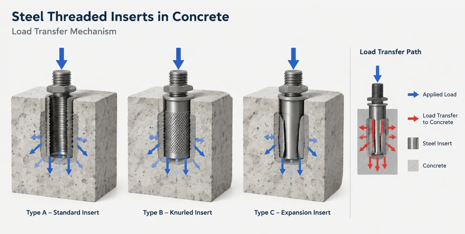
Wave-tail and rod-tail lifting inserts
Lifting inserts replace the straight foot with a wavy or bent tail that follows the stress flow of a lifting cone. They serve precast handling and temporary erection loads, where a single insert may carry the full self-weight of a panel during the turn and lift sequence. Working load limits for lifting service run from around 13 kN for small sockets to well above 100 kN for heavy precast hardware, always with the mandated safety factors against concrete and steel failure.
Flat steel and plate-end inserts
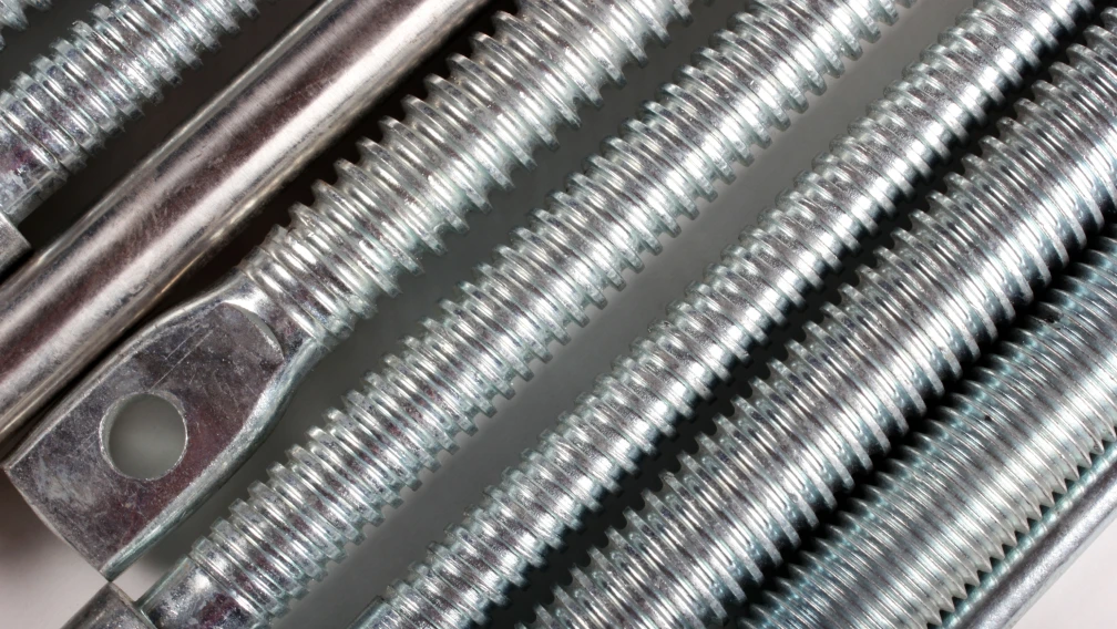
Where a slab is too thin for a long embedment, a flat steel tail or end plate spreads the load laterally instead of relying on depth. These inserts suit wall panels, stair landings, and the slab-edge fixings that later receive twin-ear anchors and tie-rod hardware for cantilevered temporary works.
| Type | Load transfer mechanism | Typical thread range | Primary application |
|---|---|---|---|
| Ferrule (socket) insert | Cross pin bears on concrete cone | M12–M24 | Brackets, supports, formwork and platform fixings |
| Wave-tail lifting insert | Shaped tail follows lifting stress cone | M12–M30 | Precast lifting and turning |
| Rod-tail insert | Straight rebar tail bonded along its length | M12–M24 | Thin slabs, edge fixings, tie-rod anchorage |
| Plate-end insert | End plate spreads load laterally | M12–M20 | Very thin elements and wall panels |
Load capacity, embedment depth, and failure modes
An insert connection can fail in four distinct ways, and the controlling mode changes with embedment depth. Steel failure of the bolt or the insert body sets the absolute ceiling and is a property of the hardware alone. Concrete cone failure, where a cone of concrete breaks out around the embedded foot, governs most shallow installations and scales with the square of the embedment depth. Pull-out failure, where the foot slips straight out without a full cone, appears when the interlock area is undersized. Pry-out and edge breakout govern inserts loaded in shear close to a free edge.
Two practical consequences follow. First, doubling embedment depth roughly quadruples the cone capacity, which is why manufacturers publish load tables keyed to embedment depth and concrete compressive strength rather than a single headline number. Second, capacity figures quoted for a 25 MPa slab cannot be transferred to a 20 MPa wall without reduction; most load tables assume normal-weight concrete at a stated strength class, and lower-strength or lightweight concrete requires a proportional down-rating.
Geometry limits complete the picture. Standard practice keeps center-to-center spacing at no less than three times the embedment depth and edge distance at no less than one and a half times the embedment depth, because overlapping stress cones shed capacity onto neighboring inserts. An insert placed 80 mm from a slab edge may develop only a fraction of the capacity of the same insert placed 200 mm in.
| Factor | Effect on working load | Field rule |
|---|---|---|
| Embedment depth | Cone capacity scales with depth squared | Specify depth from the manufacturer's load table, never by guesswork |
| Concrete strength | Capacity scales with the square root of compressive strength | Confirm pour strength class before selecting the insert |
| Edge distance | Breakout area shrinks near free edges | Minimum 1.5× embedment depth, more for shear loading |
| Spacing | Overlapping cones reduce group capacity | Minimum 3× embedment depth center-to-center |
| Reinforcement | Rebar through the cone zone raises capacity | Cross pin or tail should tie into local reinforcement where possible |
Installation workflow: from formwork to first bolt
A cast-in insert succeeds or fails before the concrete truck arrives. The standard sequence runs as follows.
- Position and mark. Transfer insert locations from the drawing to the formwork face, checking against the rebar schedule to catch interference before fixing.
- Fix the insert. Screw the insert onto a formwork installation bolt or fixing plate, then fasten the plate to the formwork. The insert must sit perpendicular to the face and tight against it, because any gap admits cement slurry into the thread.
- Protect the thread. Fit the sealing cap or foam plug supplied with the insert. A thread packed with hardened slurry rejects the bolt on stripping day.
- Tie the anchorage. Pass the cross pin or tail reinforcement through the insert and wire it to the adjacent rebar cage so vibration during the pour cannot rotate or float the insert out of position.
- Pour and vibrate with care. Direct the poker vibrator away from the insert zone; direct contact can shift the fixing or drive paste into unsealed threads.
- Strip, verify, and cap. After stripping, remove the installation bolt, check the thread with a gauge bolt, and refit a plastic cap if the connection will not be made immediately.
Common field errors and their consequences
Three errors account for most insert failures reported from site. Shallow embedment, caused by fixing to the wrong formwork face or by slumping concrete, converts a steel-controlled connection into a cone-controlled one and can halve the capacity. Thread contamination from unsealed inserts forces crews to chase threads with taps or abandon the point entirely. Rotation during vibration leaves the insert tilted in the concrete, so the bolt enters at an angle, seats unevenly on its flat washer, and loses clamping force under vibration in service.
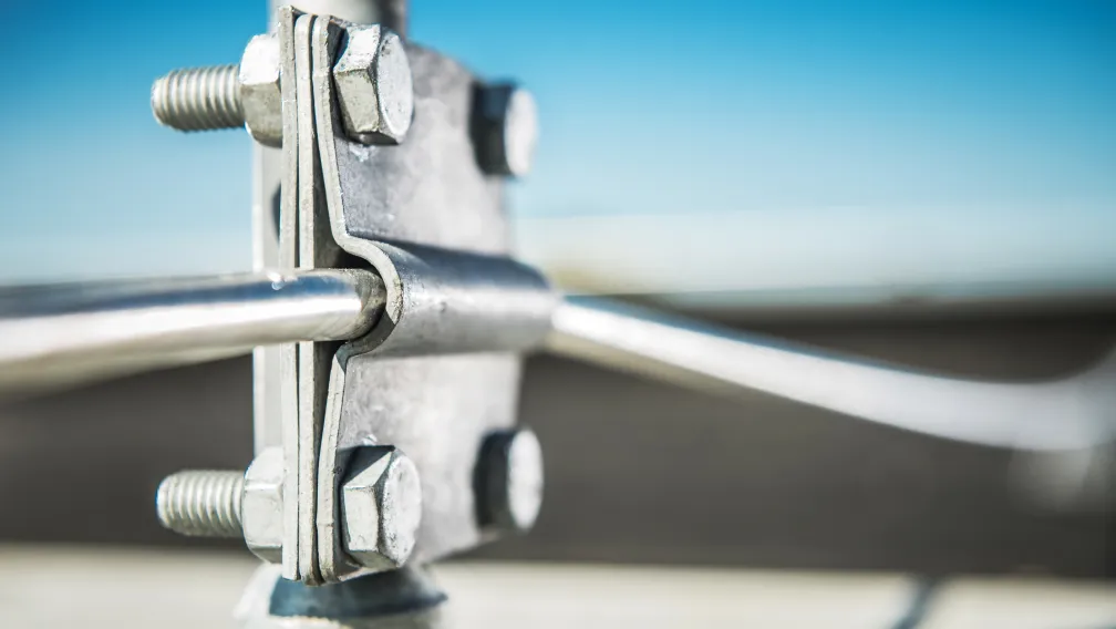
A fourth error belongs to procurement rather than the pour: pairing inserts with unmatched bolts. The internal thread is manufactured to a specific tolerance class, and a bolt from an unrelated source may start cleanly but bind or strip under torque. Inserts and bolts should arrive as a verified set.
Typical applications in structural and temporary works
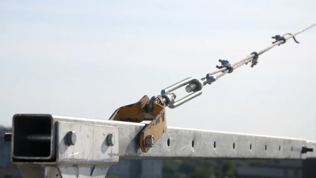
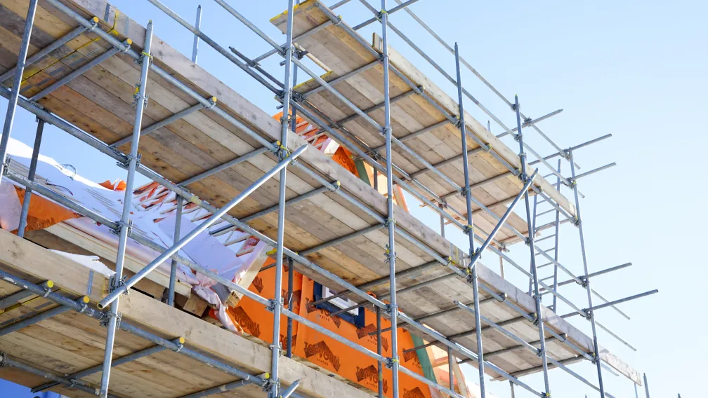
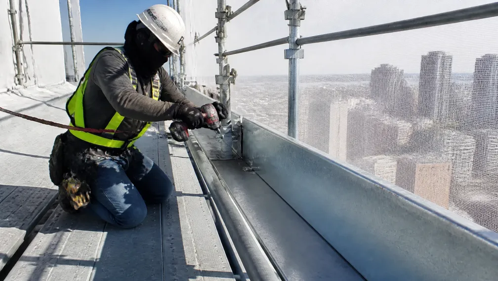
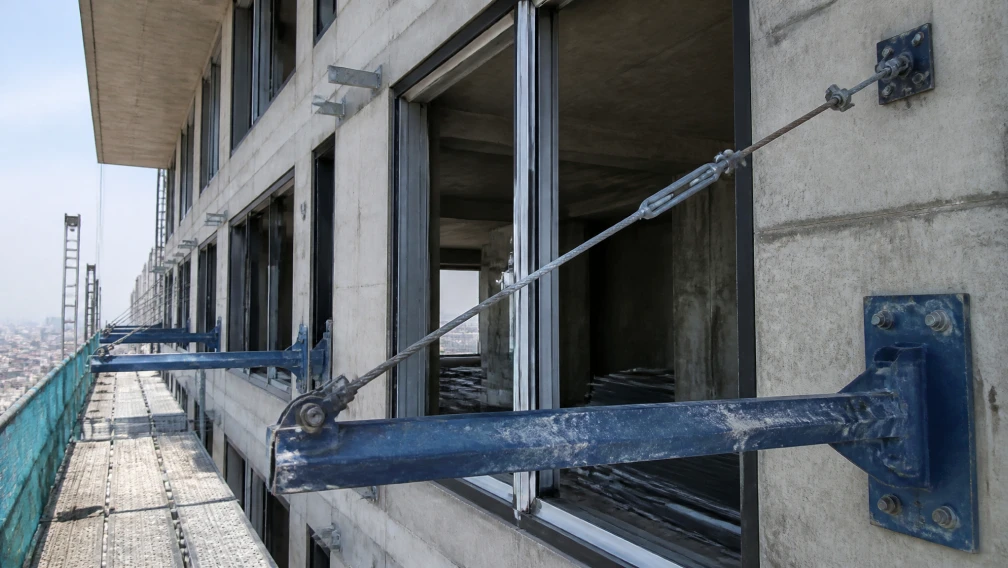
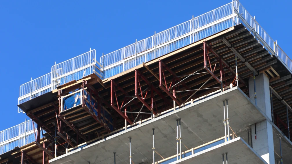
The same insert body serves permanent and temporary fixings across a project. In the permanent structure, inserts receive pipe hangers, curtain wall brackets, and machine bases. In temporary works, they anchor the slab-side end of cantilever systems: the frames of material loading platforms bolt through the slab into cast-in threads, and the inboard ends of cantilever scaffolding beams anchor the same way. In both cases the insert converts a smooth slab into a rated fixing point with no drilling, no dust, and no risk to post-tensioning tendons, provided positions were fixed before the pour.
Procurement verification checklist
- Load test data. Manufacturer tables stating working loads by thread size, embedment depth, and concrete strength class, backed by physical pull-out test reports rather than calculation alone.
- Material traceability. Mill certificates for the insert steel and the cross pin, confirming the declared grade on the actual production batch.
- Thread tolerance. Threads gauged to a stated tolerance class, with sample bolts from the same supplier verified by hand and torque wrench.
- Surface protection. Zinc plating or hot-dip galvanizing specified to the service environment; embedded steel in exterior slabs faces decades of moisture exposure.
- Complete fixing kits. Inserts delivered with matching installation bolts, sealing caps, and cross pins, so nothing is improvised on the formwork deck.
Working with Lengge
Lengge manufactures concrete threaded inserts in the standard M12 to M24 range together with the formwork installation bolts, cross pins, sealing caps, washers, and nuts that complete the connection, produced in our Hebei facility and supplied to precast plants, contractors, and distributors in more than 50 countries. Load tables and pull-out test reports accompany every batch.
Send your slab thickness, concrete strength class, and required working load through the contact page, and our team will return the insert specification, embedment depth, and quotation for your project.
-

Lengge
Cantilever Scaffolding System Manufacturer
Lengge is a China-based factory producing cantilever I-beams, tie rods, couplers, embedded parts and full scaffolding accessories. We supply contractors, wholesalers and rental companies in over 50 countries from our own production facility in Hebei.