LANGUAGE


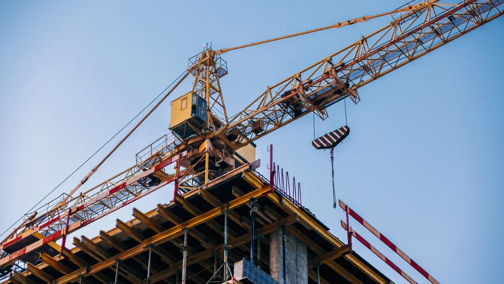
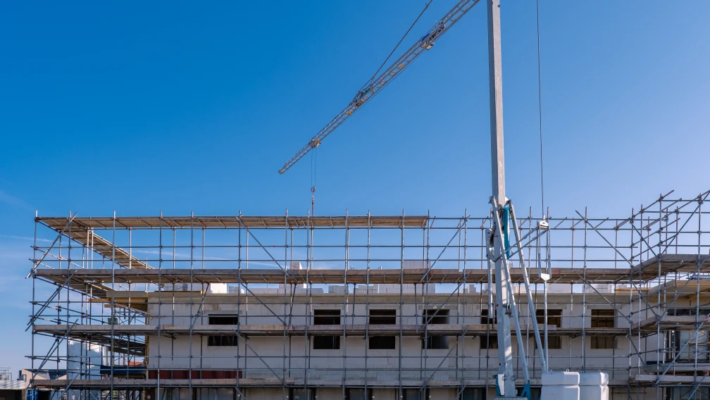
High-rise construction relies on continuous vertical logistics to maintain schedule efficiency. Tower cranes require designated landing zones at elevated floor levels to deliver formwork components, structural steel, and interior fit-out materials. Without temporary outboard structures, distributing materials to upper floors becomes a severe logistical bottleneck. A engineered material loading platform resolves this by extending a rated deck beyond the building perimeter, providing a safe, temporary landing zone for heavy loads dropped by cranes or hoists.
This technical guide examines the structural mechanics of cantilevered material loading platforms, load capacity verification, proper anchoring techniques using adjustable support systems, common failure modes identified on construction sites, and the procurement standards necessary to ensure vertical logistics remain uninterrupted and compliant with site safety regulations.
Direct Answer: What is a material loading platform?
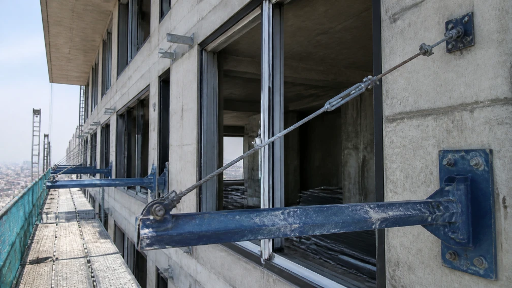
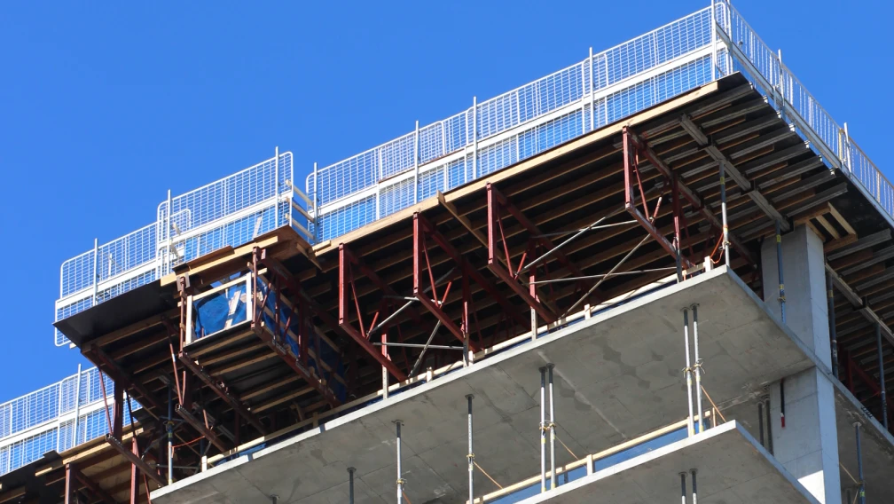
A material loading platform, frequently referred to as a crane deck or cantilever loading platform, is a temporary structural steel framework that projects from the edge of a building under construction. It provides an outboard landing area for tower cranes to deliver or remove heavy materials. The platform transfers the downward force of the load and the resulting overturning moment into the existing concrete floor slabs through a combination of heavy-duty steel beams and vertical shoring mechanisms. Standard platforms are rated for Safe Working Loads (SWL) ranging from 2,500 kg to 5,000 kg, and are engineered to withstand both the static weight of landed materials and the dynamic impact forces generated during crane unloading operations.
Core Components and Structural Design
The Main Steel Frame and Decking
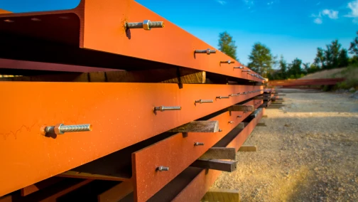
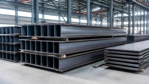
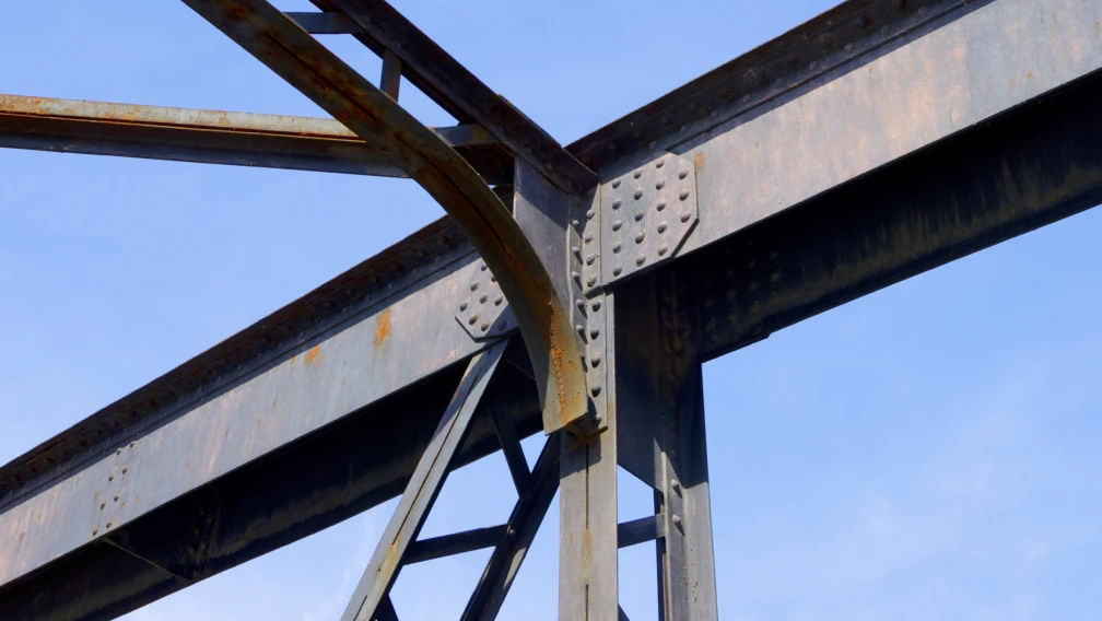
The structural integrity of a loading platform begins with its main structural members. Typically constructed from heavy-grade H-section steel or heavy universal beams, the primary cantilever beams provide the necessary rigidity to resist extreme bending moments. These longitudinal beams project beyond the slab edge, while the inboard sections rest firmly on the concrete deck to distribute the counter-balancing loads.
The working surface is universally fabricated from anti-slip steel checker plate. This decking is fully continuously welded to the underlying transverse joists. The decking must not only support the Uniformly Distributed Load (UDL) of stacked materials but also resist severe point loading from the wheels of pallet jacks or material trolleys moving across the surface. Perimeter protection is integrated directly into the steel frame, consisting of structural steel guardrails, solid steel kickboards, and safety harness anchor points.
The Inboard Anchoring System
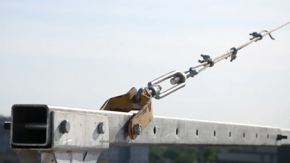
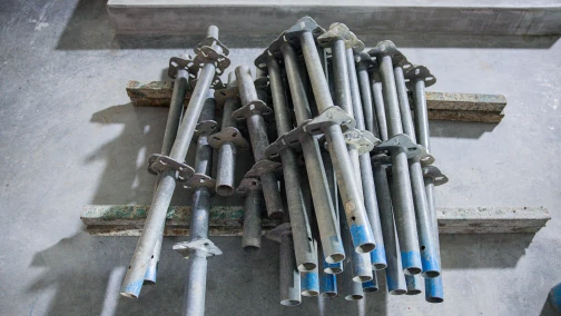
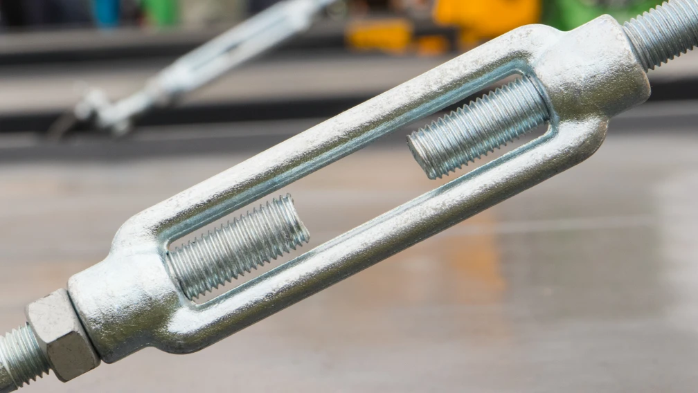
The cantilever design inherently creates an overturning moment when a load is placed on the outboard deck. This moment is neutralized by securing the inboard section of the platform to the building structure. The most common and versatile method utilizes heavy-duty adjustable steel props. These props are installed vertically between the inboard beams of the platform and the concrete soffit (the ceiling) of the floor above. By applying upward compressive force against the slab above, the props lock the platform beams against the floor below, relying on friction and structural compression to prevent the platform from tipping.
In situations where the overhead slab is absent, insufficient in strength, or too high to prop against, the platform must be anchored directly into the floor slab it rests upon. This is achieved using heavy-duty concrete threaded inserts cast into the slab during pours, or post-installed heavy-duty expansion or chemical anchors bolted through the platform's rear anchoring flanges.
Retractable Versus Fixed Platform Systems
Material loading platforms are categorized into two primary mechanical variants, each serving distinct logistical phases of high-rise construction.
- Fixed Cantilever Platforms: These are static structures bolted or propped into position. They provide a rigid, unmoving landing zone. Because they do not move, cranes must have a clear vertical path to lower loads onto them, meaning platforms on different floors are typically staggered around the building perimeter to prevent higher platforms from blocking access to lower ones.
- Retractable (Rolling) Platforms: These systems consist of a static inboard frame fixed to the slab and a rolling outboard deck. The deck can be manually extended out of the building to receive a load from the crane, and then retracted back inside the building envelope. Retractable platforms allow multiple decks to be stacked vertically in a single column on the building facade. When a lower floor needs a delivery, the platforms above it simply retract, clearing the crane's load path.
Load Capacities and Verification Standards
Platform capacities are defined strictly by their Safe Working Load (SWL). The engineering calculations must account for the static weight of the maximum intended load, plus an internal safety factor for the dynamic impact that occurs when a crane lowers a heavy pallet onto the deck.
Platform load ratings are divided into two distinct zones:
- Outboard Capacity: The load rating of the section projecting outside the building. This is heavily restricted by the bending capacity of the cantilever beams and the integrity of the rear anchor points. A common SWL for this zone is 2,500 kg to 5,000 kg.
- Inboard Capacity: The load rating of the deck section resting directly on the solid concrete floor slab. This zone typically matches the structural rating of the building's floor slab itself and can safely handle higher load concentrations, provided the building engineer approves.
Design verification requires rigorous compliance with local temporary works standards (such as AS 3610 in Australia, or BS 5975 in the UK). Load testing involves applying dead weights significantly exceeding the rated SWL to a prototype platform to measure deflection and confirm that the elastic limit of the H-section steel is not breached.
Installation Sequence and Safety Protocols
The installation of a material loading platform is a high-risk operation requiring strict adherence to an engineered lift plan.
- Pre-Installation Assessment: The project structural engineer must verify that the concrete floor slab and the soffit above have achieved sufficient curing strength (typically minimum 25 MPa) to withstand the point loads exerted by the platform beams and the compressive forces of the adjustable props.
- Lifting and Positioning: The platform is slung using certified four-point lifting chains attached to engineered lifting lugs on the platform frame. The crane maneuvers the module into the building edge, landing the inboard beams flat onto the concrete slab.
- Engaging the Props: Once positioned, high-capacity adjustable steel props are positioned vertically on the designated load-bearing points of the inboard beams. The props are extended upward until they make firm, flat contact with the concrete soffit above.
- Tensioning and Locking: The props are tensioned to the specific torque or compression rating specified by the manufacturer's engineering drawings. Mechanical locking pins are engaged to prevent accidental unthreading.
- Leveling Verification: The outboard deck must be checked to ensure it sits perfectly level or with a slight engineered upward camber (often 1-2 degrees) to compensate for expected deflection when under maximum load.
- Inspection and Sign-off: A competent temporary works supervisor inspects the prop tension, perimeter guardrails, and structural welds. The platform is tagged with a visible SWL sign before being released for use.
Common Deflection and Failure Modes
Site investigations into platform failures consistently trace back to operational deviations rather than manufacturing defects.
The primary error is point-loading the deck beyond its localized capacity. While a platform may have a total SWL of 4,000 kg, placing a 3,000 kg load on a pallet jack concentrates massive force onto four small polyurethane wheels. This can cause the checker plate decking to yield and permanently deform, even if the main H-beams are entirely unaffected.
A second common failure relates to the shoring system. If the adjustable steel props are over-tightened against a \"green\" (insufficiently cured) concrete soffit, they can punch through or crack the slab above. Conversely, if props are under-tightened, the overturning moment will cause the inboard section to lift slightly under load, resulting in severe dynamic bouncing at the outboard edge and fatiguing the steel structure over time.
Finally, material loading platforms are often mistakenly used as anchorage points for cantilever scaffolding or edge protection systems not detailed in the original engineering plan. Introducing lateral wind loads or secondary structural loads to a platform designed strictly for vertical material handling voids the engineering certification immediately.
Procurement Verification Checklist
When sourcing temporary material loading platforms, procurement teams must demand rigorous documentation to ensure structural compliance.
| Verification Category | Required Documentation | Purpose |
|---|---|---|
| Material Traceability | Mill Certificates for structural steel (e.g., Q345B / S355 grade) | Verifies yield strength of main cantilever beams. |
| Weld Integrity | NDT (Non-Destructive Testing) reports on critical load-path welds | Ensures penetration and absence of micro-cracking at primary joints. |
| Design Certification | Engineering calculations signed by a chartered structural engineer | Confirms SWL, UDL, and point-load capacities against national codes. |
| Surface Treatment | Paint thickness report or Hot-Dip Galvanizing ISO 1461 certificate | Guarantees corrosion resistance for multi-year exterior deployment. |
| Shoring Components | Load test certificates for the accompanying adjustable steel props | Verifies compressive capacity of the overturning moment restraints. |
Working with Lengge
Lengge engineers and manufactures heavy-duty material loading platforms alongside our comprehensive range of formwork components, shoring props, and scaffolding systems in our Hebei manufacturing bases. Every platform module is fabricated using fully traceable structural steel, subjected to strict weld testing, and supplied with complete load rating documentation to facilitate rapid engineering sign-off on your project sites.
For detailed technical specifications, SWL charts, or to discuss custom dimensional requirements for your upcoming high-rise logistics planning, please submit your project requirements through our contact page. Our technical engineering team will return a precise structural proposal matched to your logistical demands.
-

Lengge
Cantilever Scaffolding System Manufacturer
Lengge is a China-based factory producing cantilever I-beams, tie rods, couplers, embedded parts and full scaffolding accessories. We supply contractors, wholesalers and rental companies in over 50 countries from our own production facility in Hebei.