LANGUAGE


Pouring heavy structural concrete walls introduces extreme hydrostatic forces against the temporary formwork panels. Wet concrete acts as a dense, viscous liquid, exerting massive lateral pressure that pushes outward on the form face. If the mechanical tension system restraining these panels fails, the result is a "blowout"—a catastrophic structural failure where tons of liquid concrete rupture the formwork, destroying the pour, halting the construction schedule, and posing severe safety risks to site personnel. The primary defense against lateral concrete pressure is the formwork tie rod system.
This engineering guide dissects the physical mechanics of formwork tie rods. It details the methodology for calculating lateral concrete pressure and the corresponding tensile loads exerted on individual tie assemblies. By examining the metallurgical properties of high-tensile steel rods, ductile iron wing nuts, and heavy-duty flat washers, structural engineers and procurement managers can specify the correct tension hardware to eliminate blowout risks during deep, high-velocity concrete pours.
Direct Answer: What is a formwork tie rod system?
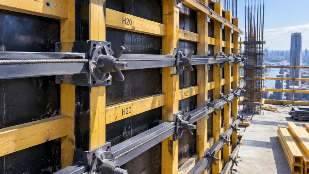
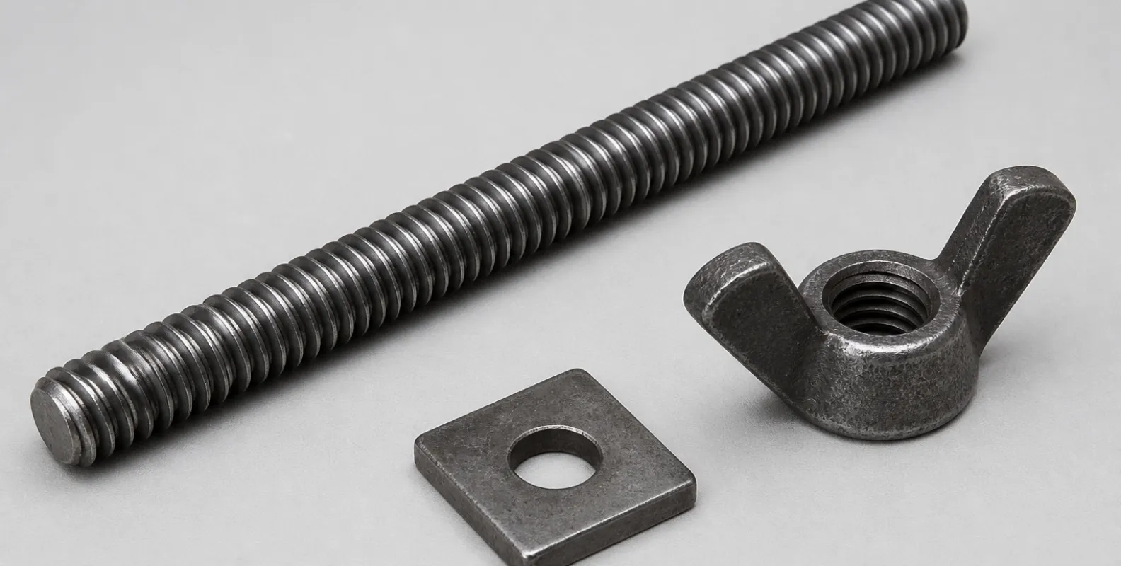
A formwork tie rod system is a temporary mechanical tension assembly designed to hold opposing concrete formwork panels in place against the severe lateral hydrostatic pressure of wet concrete. The system primarily consists of a high-tensile threaded steel bar (the tie rod) that passes through the formwork cavity, secured on both exterior faces by cast ductile iron wing nuts and heavy steel flat washers bearing against the formwork walers. Operating strictly in axial tension, the tie rod system prevents the formwork from expanding or blowing out during the pour. Standard systems utilize coarse-threaded 15/17mm rods rated for Safe Working Loads (SWL) ranging from 90 kN to 120 kN, depending on the steel grade, ensuring absolute geometric stability of the concrete wall until curing is complete.
The Physics of Wet Concrete: Lateral Pressure Dynamics
Before specifying the tension hardware, engineers must calculate the extreme force pushing against the formwork. Wet concrete exerts hydrostatic pressure similar to a liquid. The maximum pressure occurs at the bottom of the formwork and scales dynamically based on the pour height, the rate of placement, the concrete mix density, and the temperature.
According to standards such as ACI 347R-14 (Guide to Formwork for Concrete), liquid concrete possessing a standard density of roughly 2,400 kg/m³ exerts a lateral pressure that can be simplified in static fluid mechanics as:
$$ P = \rho \cdot g \cdot h $$
Where $P$ is the hydrostatic pressure in kilopascals (kPa), $\rho$ is the density of the wet concrete, $g$ is gravity (9.81 m/s²), and $h$ is the vertical height of the liquid concrete head. A wall poured continuously to a height of 3.0 meters can generate bottom pressures exceeding 70 kPa. If internal vibrators are deployed aggressively to consolidate the mix, this pressure is amplified. The formwork tie rod system must be mathematically engineered to absorb this peak pressure transferring through the plywood and timber walers.
Calculating the Tensile Load per Tie Rod Assembly
The total lateral force of the concrete is distributed across a grid of tie rods. To determine the axial tension applied to a single tie rod, engineers calculate the "area of influence" managed by that specific fixing point. The area of influence is the horizontal spacing between the tie rods multiplied by the vertical spacing between the walers.
If a formwork design specifies tie rods spaced 0.8 meters horizontally and 0.6 meters vertically, the area of influence for one tie rod is $0.8 \text{ m} \times 0.6 \text{ m} = 0.48 \text{ m}^2$.
Assuming the maximum calculated concrete pressure at the bottom of the wall is 75 kPa ($75 \text{ kN/m}^2$), the total tensile force ($F$) attempting to snap that specific bottom tie rod is:
$$ F = 75 \text{ kN/m}^2 \times 0.48 \text{ m}^2 = 36 \text{ kN} $$
The tie rod assembly must possess a Safe Working Load (SWL) comfortably exceeding 36 kN. Formwork codes universally demand a safety factor (typically 2.0) applied against the ultimate tensile breaking strength of the rod to account for dynamic pump surges and uneven tightening.
Components of the Tension System and Failure Limits
A tension system is only as strong as its weakest interlocking component. A formwork tie consists of three critical metallurgical elements, each presenting a distinct failure mode if improperly specified.
1. The High-Tensile Scaffold Tie Rod
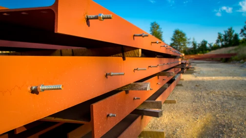
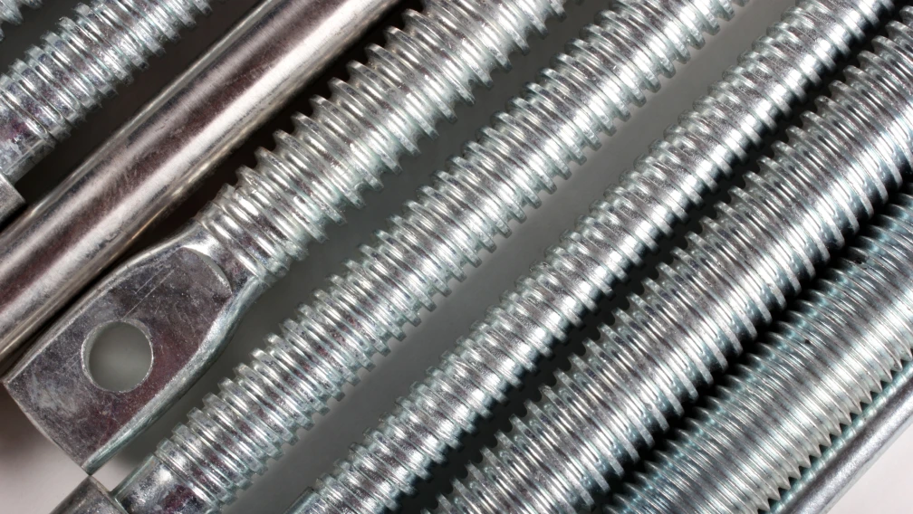
The central spine of the system is the scaffold tie rod. Standard construction utilizes 15/17mm diameter rods featuring a very coarse, fast-pitch thread (often referred to as a Dywidag-style thread). This coarse pitch allows concrete splatter to be easily knocked off and enables rapid running of the wing nuts.
Tie rods are manufactured in two distinct rolling processes affecting their capacity. Cold-rolled rods (often Q235 or 45# carbon steel) provide a moderate yield strength suitable for standard retaining walls, offering breaking loads around 90 kN to 110 kN. For heavy civil engineering, hot-rolled tie rods utilizing high-alloy steels (like 42CrMo or PSB830) deliver extreme yield limits, pushing ultimate breaking strengths to 190 kN. If a tie rod yields (stretches plastically), the formwork wall bulges permanently. If it snaps, a blowout is immediate. Procurement must align the rod's metallurgy strictly with the calculated $F$ value.
2. The Ductile Iron Wing Nut
The tensile load from the steel rod must be locked off on the outside of the formwork. This is achieved using a scaffold wing nut. The wing nut engages the threads of the tie rod and bears the entire axial load transferring from the expanding wall.
Because wing nuts are subjected to brutal impact forces from site workers hammering the "wings" to tighten or loosen them, they must be manufactured from cast ductile iron (e.g., QT450-10). Ductile iron possesses a nodular graphite microstructure, allowing it to absorb hammer strikes and extreme tension without shattering. Cheap wing nuts cast from brittle grey iron will physically crack and shear off the rod under high hydrostatic pressure, acting as the primary trigger for formwork blowouts. The internal thread depth of the wing nut must match the tie rod pitch exactly to prevent thread stripping under load.
3. The Load-Distributing Flat Washer
The extreme tension concentrated at the wing nut must be spread evenly across the timber or steel walers holding the formwork panels. Applying a wing nut directly to a timber waler without a flat washer causes localized crushing. As the timber crushes, the tie rod loses its initial tension, allowing the formwork to "breathe" and expand during the pour.
Heavy-duty flat washers (typically 120mm x 120mm x 10mm thick) act as the vital bearing plates. They increase the surface area of the load transfer, dropping the bearing stress on the wood well below its compressive yield limit. If the flat washer is manufactured too thin, it will buckle and dish inward under the pressure of the wing nut, leading to identical tension loss and wall bulging.
Dynamic Factors Causing Blowouts on Site
Engineering calculations assume ideal conditions. Formwork blowouts on construction sites generally occur when operational realities deviate from the mathematical model. The most frequent error is exceeding the designed pour rate. If the concrete pump fills the formwork faster than the concrete can begin its initial set at the bottom, the liquid head height ($h$) increases rapidly, exponentially raising the hydrostatic pressure beyond the tie rod's SWL.
Vibration protocols also introduce dynamic risk. While poker vibrators are necessary to remove air voids and consolidate the concrete, holding a high-frequency vibrator too close to the formwork face or deep within the bottom layers re-liquefies the curing concrete. This sudden re-liquefaction spikes the lateral pressure, often shocking the tie rod threads and causing overloaded, fatigued wing nuts to strip instantly.
Finally, the reuse of tie rods introduces microscopic fatigue. Every time a rod is stretched near its yield limit and relaxed, its crystalline structure suffers. Bent tie rods hammered straight by yard workers contain severe stress risers. Deploying fatigued, straightened rods at the bottom of a deep formwork pour invites catastrophic failure. Professional contractors establish strict usage cycles and quarantine protocols for heavily cycled tension rods.
Procurement Verification Checklist for Tension Systems
Acquiring reliable formwork tension hardware requires strict metallurgical verification prior to deployment.
- Tensile Test Certificates: Demand independent laboratory destruction tests proving the tie rod and wing nut assembly achieves the specified ultimate breaking load (e.g., 140 kN minimum for heavy duty).
- Thread Compatibility: Ensure the tie rods and wing nuts are procured as an integrated set. Mismatched thread pitches from different suppliers will bind or strip prematurely under torque.
- Ductile Iron Verification: Require mill certificates confirming the wing nuts are cast from QT450-10 ductile iron (or equivalent), avoiding brittle grey iron components.
- Washer Plate Thickness: Confirm flat washers are pressed from Q235 steel with a minimum thickness of 8.0 mm to prevent localized buckling against the walers.
- Elongation Metrics: Verify the steel tie rod exhibits sufficient ductility (elongation percentage) in the mill test report, ensuring the rod stretches visibly before snapping, providing critical warning of a potential blowout.
Working with Lengge's Formwork Engineering Division
Lengge is a primary manufacturer of structural formwork accessories, engineering high-tensile tie rod systems that protect major civil construction projects against blowout failures. Our facilities produce precision cold-rolled and hot-rolled 15/17mm tie rods, paired exclusively with heavy-duty QT450 ductile iron wing nuts and thick steel bearing washers. Every production batch is subjected to relentless destruction testing in our in-house laboratories, guaranteeing documented Safe Working Loads that site engineers can rely upon.
To submit your formwork pressure calculations, request detailed tensile test reports, or procure fully certified tie rod assemblies for your upcoming concrete walls and columns, engage with our technical team via our contact page. We provide direct factory supply to heavy construction contractors and formwork rental fleets worldwide.
-

Lengge
Cantilever Scaffolding System Manufacturer
Lengge is a China-based factory producing cantilever I-beams, tie rods, couplers, embedded parts and full scaffolding accessories. We supply contractors, wholesalers and rental companies in over 50 countries from our own production facility in Hebei.