LANGUAGE


The mechanical limits of standard profiles in wide-span cantilevers
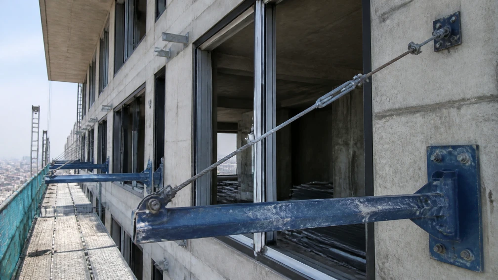
Erecting high-rise temporary staging systems demands structural foundations capable of resisting multi-axial forces. When site engineers design a cantilever scaffolding network, they project steel beams outward from the building's concrete edge to act as the primary load-bearing foundation. For narrow perimeter scaffolds extending 1.0 to 1.5 meters into open airspace, standard hot-rolled I-beams fulfill the basic deflection and shear requirements.
However, modern mega-towers frequently demand wide-span staging areas, multi-tier hanging drop-scaffolds, and heavy logistics transfer decks that project 2.5 to 4.0 meters outward. As the projection distance (the lever arm) increases, the bending moment generated by the suspended load scales exponentially. Standard I-beams lack the cross-sectional mass distribution necessary to combat these extreme rotational forces. Under heavy eccentric loading or high-altitude wind shear, standard narrow-flange I-beams become highly susceptible to lateral-torsional buckling—a catastrophic failure mode where the beam twists sideways and collapses before reaching its ultimate tensile yield limit. To neutralize this twisting hazard, structural engineers mandate the deployment of heavy-duty H-section steel profiles.
Direct Answer: What is H-section steel in scaffolding?
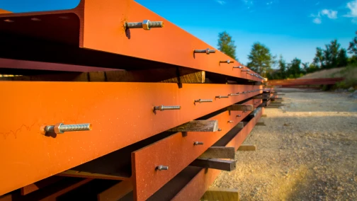
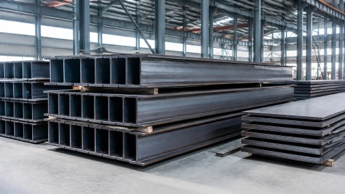
H-section steel is a high-efficiency structural steel profile manufactured with wide, parallel flanges and a web-to-flange thickness ratio that creates an "H" shape. Unlike standard I-beams which feature narrow, tapered inner flanges, H-section steel distributes its metallic mass further away from the central neutral axis along both the X and Y axes. In cantilever scaffolding applications, this specific geometric distribution provides massive sectional inertia, rendering the outrigger beam highly resistant to lateral-torsional buckling, web crippling, and extreme bending moments. Manufactured typically from Q355B low-alloy high-strength steel, H-sections form the unyielding foundation for wide-span staging decks and heavy-duty material loading platforms.
Geometric cross-section comparison: Parallel versus tapered flanges
The defining physical difference between an H-beam and a traditional cantilever I-beam lies in the geometry of the horizontal flanges. A traditional hot-rolled I-beam (such as a standard 18# profile) is produced with tapered inner flanges. The steel is thickest where the flange meets the vertical web and tapers thinner toward the outer edge. This slope (typically ranging from 1:6 to 1:10) introduces mechanical complications during erection. When workers attempt to bolt flat anchor plates or secure structural clamps to an I-beam, the tapered surface causes the bolt heads to seat at an angle, inducing eccentric bending stress into the fasteners unless specialized beveled washers are procured.
An H-section steel profile features flanges that are perfectly flat and strictly parallel on both the inner and outer surfaces. This parallel geometry guarantees that heavy twin-ear anchoring lugs and heavy-duty scaffold beam clamps achieve 100% flush surface contact. The elimination of tapered gaps ensures pure frictional clamping and allows site workers to achieve the mandated 50 Nm installation torque without inducing angular shear stress on the T-bolts.
Section Modulus ($W_x$ and $W_y$) and resisting bending moments
The structural capacity of a cantilever outrigger is calculated using its Section Modulus ($W$), a geometric property indicating a cross-section's resistance to bending. Engineers calculate bending resistance across two primary axes: the strong axis ($X-X$, resisting vertical gravity loads) and the weak axis ($Y-Y$, resisting lateral horizontal loads like wind shear).
Standard I-beams possess a relatively high $W_x$ but an extremely low $W_y$ due to their narrow flanges. They resist gravity adequately but fail rapidly when pushed sideways. H-section steel is explicitly engineered to maximize both values. Because the flanges of an H-beam are significantly wider—often equaling the depth of the web in specific profiles (such as HW series)—the mass is pushed to the extreme perimeter of the geometric cross-section. An HW200x200 profile offers a weak-axis section modulus ($W_y$) nearly triple that of a standard 20# I-beam. This massive multi-axial rigidity ensures the scaffolding foundation remains absolutely immobile, even when subjected to 120 km/h hurricane-force lateral wind gusts.
Lateral-Torsional Buckling (LTB) under eccentric wind loads
When a cantilever beam is loaded vertically downward, the top flange operates under high compression, while the bottom flange operates in tension. Steel in tension remains straight, but steel in compression naturally wants to buckle (bend away from the load). Because the top flange is essentially a slender steel column acting in compression, it attempts to buckle sideways.
If the beam lacks lateral stiffness, the top flange will suddenly swing to the left or right, dragging the vertical web with it and causing the entire beam to twist spirally. This is Lateral-Torsional Buckling (LTB). LTB is the most common failure mode for deep, narrow outrigger beams. H-section steel neutralizes LTB entirely through its wide horizontal flanges. The wide flanges provide massive lateral stiffness, mathematically shifting the LTB failure threshold far beyond the ultimate vertical yield strength of the steel. This allows structural engineers to push the cantilever projection outward to 3.0 or 4.0 meters without requiring continuous, complex cross-bracing between the outrigger beams.
The mathematics of the unbraced length ($L_b$) in projecting cantilevers
To calculate the risk of buckling, structural engineers evaluate the unbraced length ($L_b$) of the cantilever. $L_b$ is defined as the physical distance between two points where the top compression flange is rigidly restrained from moving laterally. Inside the building, the outrigger beam is bolted to the concrete slab; outside the building, it projects into open air.
For a standard staging system projecting 3.0 meters outward, the unbraced length is exactly 3.0 meters. The longer the unbraced length, the lower the beam's capacity to resist compressive buckling before twisting. H-section steel possesses a massive radius of gyration about the weak axis ($r_y$). Since the critical buckling stress of a beam is inversely proportional to the square of its slenderness ratio ($L_b/r_y$), utilizing an H-beam with a large $r_y$ exponentially increases the load the cantilever can safely bear over long, unbraced spans.
Flange local buckling (FLB) and width-to-thickness ratios
Beyond global twisting, the individual plates comprising the beam face localized failure risks. If the horizontal flanges of an outrigger are excessively wide but manufactured too thin, the edges of the flange will ripple or fold under extreme compressive stress—a phenomenon known as Flange Local Buckling (FLB).
Structural steel codes classify profiles as "compact," "non-compact," or "slender" based on the width-to-thickness ratio ($b/t$) of their flanges. Professional B2B procurement mandates the use of strictly "compact" H-section profiles for cantilever staging. Compact sections guarantee that the steel flanges will physically reach their ultimate yield point (e.g., 355 MPa) and undergo significant plastic deformation before any localized rippling occurs. This provides a massive, visually obvious safety margin, warning site inspectors of an overload condition long before a sudden catastrophic snap.
Yield strength metallurgy: Q355B low-alloy carbon steel specifications
The geometric advantages of the H-shape are nullified if the base metallurgy is inadequate. Budget steel suppliers routinely roll structural profiles from Q235B mild steel. Mild steel offers a minimum yield strength of 235 MPa, which is insufficient for the extreme bending moments of wide-span cantilever staging.
Tier-one engineering specifies Q355B (equivalent to European S355JR or American ASTM A572 Grade 50) for all primary H-section outriggers. Q355B is a low-alloy high-strength steel. The chemical addition of elevated manganese (up to 1.60%) and trace micro-alloying elements like niobium and vanadium refines the internal grain structure of the steel during hot-rolling. This raises the absolute minimum yield strength to 355 MPa for sections up to 16mm thick. Specifying Q355B grants the staging network a 50% increase in structural capacity over Q235B without adding a single kilogram of dead weight to the assembly.
Web crippling and localized crushing forces at the slab edge
When the cantilever outrigger bears a heavy load on its tip, it pivots against the edge of the building's concrete slab. The entire downward force of the outboard deck, combined with the extreme tension of the inboard anchor bolts, concentrates on a tiny contact area exactly where the steel web crosses the concrete edge.
This extreme concentrated reaction force attempts to physically crush the vertical web of the H-beam, folding it like an accordion. This failure mode is defined as web crippling. The resistance to web crippling is dictated directly by the thickness of the vertical web ($t_w$) and the steel's yield strength. H-section steel profiles are rolled with web thicknesses specifically proportioned to their flange widths, ensuring they possess the necessary compressive mass to sit directly on sharp concrete edges without requiring supplemental stiffener plates to be welded into the web cavity on-site.
Welding twin-ear anchors to H-section flanges: HAZ management
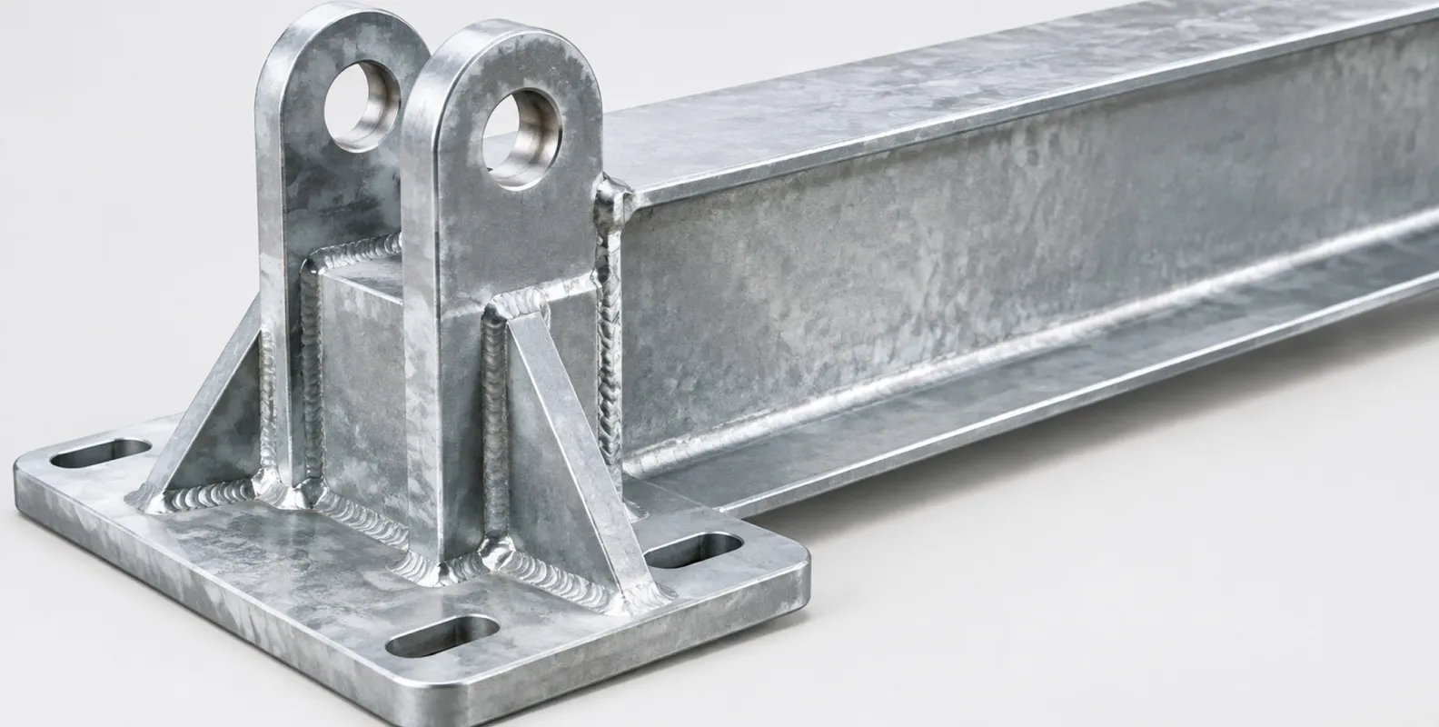
H-section outriggers do not operate in isolation; they must interact with the diagonal tension systems to arrest downward deflection. This requires welding heavy-duty twin-ear anchors directly to the top horizontal flange of the beam. The clevis pin passing through this anchor will transfer massive diagonal tension from the tie-rods directly into the steel beam.
The welding of these anchor plates involves extreme localized heating. As the weld pool hits 1,500°C, the surrounding Q355B steel undergoes a metallurgical phase change. The rapid cooling of the thick flange creates a brittle Heat-Affected Zone (HAZ) prone to microscopic hydrogen-induced cracking. Under dynamic wind loads, these micro-cracks propagate, eventually tearing the entire twin-ear anchor off the beam. Certified factories combat this by enforcing strict pre-heating protocols (elevating the flange temperature before welding) and utilizing low-hydrogen electrodes (such as E7018) via robotic welding arms. This ensures the HAZ cools slowly, retaining the high ductility required to survive cyclic tension.
Ultrasonic Non-Destructive Testing (NDT) for flange-to-web penetration
Unlike hot-rolled sections where the web and flanges are extruded seamlessly from a single steel billet, customized extreme-heavy H-sections are occasionally fabricated by welding three separate steel plates together (a built-up section). The mechanical integrity of a built-up H-beam relies 100% on the continuous longitudinal welds connecting the web to the top and bottom flanges.
Visual inspection cannot confirm if the weld has penetrated entirely through the root of the joint. To guarantee structural safety on fabricated outriggers, procurement managers must demand Ultrasonic Non-Destructive Testing (NDT). An operative passes an ultrasonic transducer along the flange. High-frequency sound waves travel through the steel. If the wave hits an internal air void or a lack-of-fusion defect at the web intersection, it bounces back, registering a spike on the oscilloscope. Contracts must mandate AWS D1.1 full-penetration criteria, confirmed by UT reports, before the steel leaves the factory.
Concrete breakout and anchoring base plates for H-sections
The inboard tail of the H-section beam rests inside the building and must be anchored to counteract the rotational uplift force. Typically, the beam ends in a heavy steel base plate equipped with pre-drilled slotted holes. Workers secure this plate to the floor slab using heavy chemical anchors or cast-in threaded inserts.
The ultimate failure of this inboard node rarely involves the steel plate snapping. The failure occurs in the concrete. The uplift force pulls the anchor bolts upward, ripping a massive 35-degree conical chunk of concrete out of the floor slab (conical breakout). The width of the H-section's base plate determines the spacing of the anchor bolts. A wider base plate pushes the anchor bolts further apart, ensuring their theoretical failure cones do not overlap. This maximizes the volume of concrete resisting the uplift, pushing the base anchoring capacity safely beyond the maximum operational loads of the cantilever deck.
Integration with heavy-duty material loading platforms
Beyond supporting tubular scaffolding, H-section steel serves as the primary longitudinal foundation for retractable material loading platforms. These massive outrigger decks project from high-rise facades to receive heavy pallets of bricks and machinery lowered by tower cranes.
When a tower crane lands a 3-ton pallet onto the outboard deck, the sudden deceleration generates extreme dynamic shock loads, multiplying the static weight by a factor of 1.30 or higher. The primary support beams must absorb this kinetic energy without yielding. H-section profiles provide the necessary multi-axial rigidity. The wide upper flanges provide a vast, flat surface area to securely weld the steel chequer plate decking, while the thick vertical webs effortlessly transfer the massive point-loads of the crane impact backward into the building's concrete core.
Thermal expansion and contraction in exposed exterior steel
Cantilever outriggers operate completely exposed to the elements. During a high-rise construction cycle, the steel temperature can fluctuate from -10°C in the winter to +60°C under direct summer sunlight. Steel expands and contracts strictly according to its coefficient of thermal expansion.
A 6.0-meter H-section beam will expand linearly by several millimeters under extreme heat. If the inboard base plate is bolted rigidly to the concrete floor using exact-fit circular holes, this thermal expansion generates massive internal shear stress against the anchor bolts. The expanding steel acts as a hydraulic ram, eventually shearing the bolts or cracking the concrete slab. To neutralize thermal stress, the base plates of professional H-section outriggers are CNC-machined with slotted holes (elongated longitudinally). The high-tensile anchor bolts are torqued securely, but the slotted holes allow the steel beam to micro-slide forward and backward during thermal shifts without transferring any destructive shear force into the concrete floor.
Hot-Dip Galvanizing (HDG) thick sections: Warping and hydrogen embrittlement
To survive a 10-year rental lifecycle without rusting, structural outrigger beams are subjected to Hot-Dip Galvanizing (HDG). Submerging a massive H-section beam into a 450°C zinc bath introduces severe thermal shock. If a beam is manufactured with built-in residual stresses from cold-rolling or uneven welding, the extreme heat of the zinc bath will release these stresses instantly, causing the heavy steel beam to warp, twist, or bow out of plumb permanently.
Furthermore, the acid pickling process used to clean the steel prior to galvanizing introduces hydrogen atoms into the metallic grain structure. For high-tensile steel (exceeding 800 MPa), this causes hydrogen embrittlement, causing the steel to shatter under load. While standard Q355B structural steel is generally immune to severe hydrogen embrittlement, the welding zones require careful management. Professional galvanizers dip the beams at controlled speeds and angles to manage thermal expansion evenly and utilize post-dip stress-relief baking protocols to out-gas any trapped hydrogen, ensuring the H-beams return to the yard perfectly straight and mechanically sound.
Load distribution: Staggered outrigger placement vs. continuous runs
The spacing of the H-section outrigger beams dictates the structural grid of the entire facade scaffold. To maximize material efficiency, beams are typically spaced at 1.8-meter or 2.4-meter intervals, matching the standard lengths of the horizontal scaffold ledgers connecting them.
However, when a facade demands an exceptionally high scaffolding structure, the accumulated dead weight forces the outriggers to operate near their maximum Safe Working Load (SWL). If one outrigger yields, the load instantly shifts to the adjacent beams, triggering a cascading zipper-effect collapse. To build redundancy into the foundation, structural designers utilize continuous load-distribution bridging. Heavy steel channels are bolted horizontally across the top flanges of all the projecting H-beams, physically tying them together. If one H-beam experiences a localized overload from a dropped crane load, the horizontal bridging instantly redistributes the kinetic shock across the adjacent five outrigger beams, ensuring the system remains statically stable.
Deflection limits ($L/250$) and the requirement for diagonal tie-rods
Regardless of how thick the H-section web is, all projecting cantilevers deflect (bend downward) under load. International scaffolding codes dictate that the absolute downward displacement at the tip of the outrigger must not exceed $L/250$, where $L$ is the outboard projection length. For a 3.0-meter projection, the absolute maximum downward deflection is 12 millimeters.
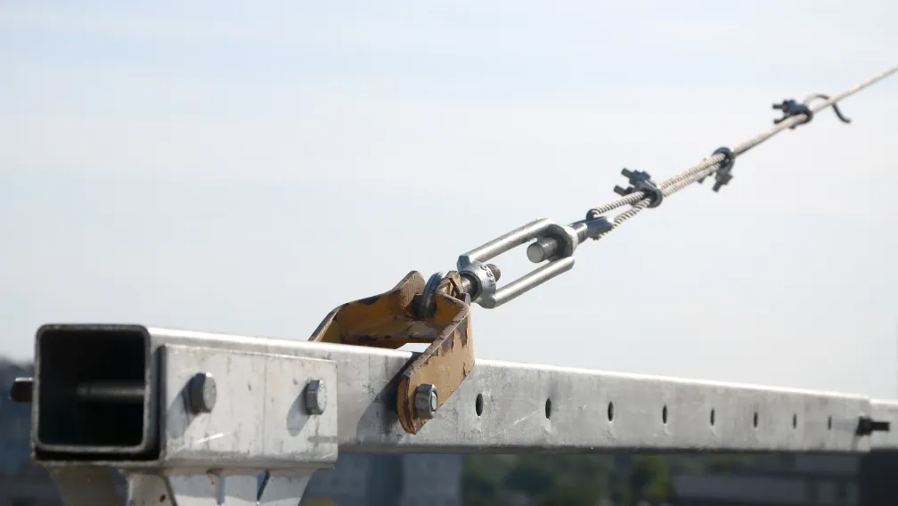
If the beam deflects 25mm, the 40-meter tall scaffolding network erected upon it will lean significantly away from the building, tearing the safety wall-ties out of the masonry. To guarantee absolute compliance with the $L/250$ deflection limit over wide spans, the H-section beam is fundamentally augmented with a diagonal tension line. A high-tensile tie-rod connects the outer tip of the H-beam to the overhead concrete wall. This tie-rod arrests the downward bending motion entirely, converting the bending stress into pure axial tension and ensuring the scaffolding foundation remains mathematically level at zero degrees.
Inspection protocols: Identifying web yielding and flange rotation
H-section outriggers are capital rental assets that suffer continuous abuse. When the beams are demobilized and returned to the staging yard, quality assurance inspectors must execute a rigorous physical audit to detect hidden fatigue before redeployment.
The primary inspection involves checking the flange-to-web intersection for 90-degree squareness. The inspector runs a specialized steel machinist's square along the beam. If the top flange has rotated (curled downward) relative to the vertical web, it indicates the beam was subjected to severe lateral-torsional forces beyond its elastic limit. Secondly, the inspector examines the vertical web directly beneath the inboard anchor points and the fulcrum contact zone. Any rippling, waviness, or compression bulges indicate the beam suffered web crippling under extreme point loads. Beams exhibiting plastic deformation, twisted flanges, or web ripples cannot be repaired by cold-hammering; they must be permanently decommissioned and scrapped.
B2B procurement fraud: Section weight tolerances and thickness cheating
The international trade of structural steel relies on standard weight-per-meter specifications. A legitimate supplier quotes a price based on the theoretical density of the steel. Unverified suppliers execute procurement fraud by exploiting negative manufacturing tolerances. They order the steel mills to roll the H-section webs and flanges significantly thinner than the specified blueprint (e.g., rolling an 8.0mm web to 6.5mm).
This shaves hundreds of kilograms of raw material cost off the bulk order, allowing the fraudulent supplier to offer an unbeatable unit price. However, reducing the flange thickness completely destroys the Section Modulus ($W_x$) of the beam, rendering the cantilever mathematically unsafe. B2B procurement managers detect this fraud by enforcing actual scaled weight mandates. If the theoretical weight of the ordered HW200x200 beam is 50.5 kg/m, a 6.0-meter beam must weigh approximately 303 kg. If the beam registers 260 kg on the receiving scale, the supplier has committed severe negative tolerance fraud. Contracts must stipulate price deductions or outright rejection for any batch falling below a strict -5% weight tolerance limit.
Evaluating pre-welded positioning pins for base fixation
To erect the vertical scaffolding standard securely onto the smooth, flat top flange of the H-section beam, there must be a physical mechanical anchor to prevent horizontal sliding. This is achieved through factory-integrated positioning pins.
Solid 36mm steel dowels are robotically welded to the top flange of the H-beam at exact grid intervals. The hollow 48.3mm vertical scaffolding tube slides entirely over this solid pin. This mechanical shear joint ensures that lateral wind loads striking the scaffolding facade cannot slide the base of the framework off the edge of the outrigger beam. Buyers must ensure these pins are 100% factory pre-welded and verified via Magnetic Particle Inspection (MPI); field-welding pins on the active jobsite guarantees misaligned grids and porous, brittle welds that will snap under shear impact.
Connect with our engineering team for certified structural outriggers
Lengge Steel manufactures certified, heavy-duty H-section steel outriggers for global cantilever scaffolding and staging logistics. Our production lines supply fully traceable Q355B H-beams, exactingly fabricated with robotic AWS D1.1 full-penetration welding, precision CNC-slotted base plates, and drop-forged twin-ear anchors. We enforce strict negative weight tolerance limits and provide premium 80-micron hot-dip galvanizing to ensure absolute structural safety and maximum rental longevity. Submit your specific facade projection lengths, target load capacities, and required staging widths to our engineering desk to receive a comprehensive structural quotation, finite element analysis (FEA) reports, and certified mill test documentation. Visit our contact page to secure your high-performance structural steel supply chain today.
Frequently Asked Questions
To determine structural sufficiency, if an outrigger beam projects 3.0 meters and must support a concentrated point load of 25 kN at its absolute tip, what is the required Section Modulus ($W_x$) assuming Q235B steel is used?
First, calculate the maximum bending moment ($M$) generated at the fulcrum (slab edge). Moment equals Force multiplied by Distance: $M = 25 \text{ kN} \times 3.0 \text{ m} = 75 \text{ kNm}$ (or $75,000,000 \text{ N\cdot mm}$). The required section modulus ($W_{x,\text{req}}$) is calculated by dividing the bending moment by the allowable stress of the steel ($\sigma_{\text{allowable}}$). For Q235B steel, the yield strength is 235 MPa; assuming a safety factor that limits working stress to roughly 215 MPa, the calculation is $W_{x,\text{req}} = 75,000,000 / 215 = 348,837 \text{ mm}^3$ (or $348.8 \text{ cm}^3$). A standard 18# I-beam possesses a $W_x$ of only 178 cm³, which is massively lower than the required 348.8 cm³. If loaded, the 18# I-beam will undergo catastrophic plastic yielding. The calculation proves that a heavy-duty H-section profile with a minimum $W_x$ of 350 cm³ (such as an HW200x200) must be specified for this load.
To verify deflection limits, if a 4.0-meter cantilever beam has a mandated $L/250$ deflection limit, what is the absolute maximum allowable downward bend at the tip?
The deflection limit calculation requires dividing the unsupported projecting length ($L$) by 250. Convert the projection to millimeters: $4.0 \text{ meters} = 4,000 \text{ mm}$. Divide 4,000 mm by 250. $4,000 / 250 = 16 \text{ mm}$. Therefore, under the absolute maximum intended working load, the physical tip of the outrigger beam must not sag downwards by more than 16 millimeters. If the static load calculations indicate the beam will sag by 25mm, the engineer must immediately integrate a diagonal tension tie-rod to arrest the deflection, regardless of whether the beam possesses the ultimate yield strength to hold the weight without breaking.
Why is Lateral-Torsional Buckling (LTB) a greater threat to standard I-beams than to H-section steel?
When a cantilever beam bends downward, the top flange is placed under extreme compression, acting like a slender horizontal column. It mathematically wants to buckle sideways to relieve the stress. Because standard I-beams feature extremely narrow top flanges, they lack the geometric mass (weak-axis inertia, $I_y$) to resist this lateral movement. The top flange kicks sideways, twisting the entire web into a spiral and collapsing the beam. H-section steel features massively wide, parallel flanges. This geometry distributes the steel mass far from the vertical center, providing immense lateral stiffness that mathematically neutralizes the LTB tendency, ensuring the beam remains vertically stable even under deep eccentric loads.
How does upgrading from Q235B to Q355B metallurgy affect the dead weight of the cantilever system?
Upgrading the steel grade alters the microscopic crystalline structure of the metal, not its density. Both Q235B mild steel and Q355B low-alloy high-strength steel possess an identical physical density of approximately $7,850 \text{ kg/m}^3$. However, Q355B utilizes chemical additives (manganese, niobium) to increase the yield strength from 235 MPa to 355 MPa—a massive 50% increase in structural capacity. Therefore, specifying Q355B grants the staging network a 50% higher resistance to bending and shearing forces without adding a single extra kilogram of dead weight to the building's floor slab or increasing the crane hoisting burden.
Why must the inboard anchoring holes on the base plate of the H-beam be slotted longitudinally?
Steel expands and contracts predictably based on its thermal coefficient. A 6.0-meter long H-section beam operating in a climate that fluctuates by 40 degrees Celsius will expand and contract linearly by several millimeters. If the base plate is bolted rigidly to the concrete floor using exact-fit circular holes, this thermal expansion acts as a hydraulic ram. The immense force generated by the expanding steel creates extreme internal shear stress against the embedded anchor bolts, eventually causing the bolts to snap or the concrete to crack. Slotted (elongated) holes allow the steel base plate to micro-slide longitudinally under thermal shifts, safely dissipating the stress while the bolts maintain downward clamping friction.
What physical mechanism causes web crippling at the concrete slab edge?
The concrete slab edge acts as the primary fulcrum for the cantilever lever. The entire downward gravity load of the outboard staging deck, multiplied by the extreme tension pulling downward on the inboard anchor bolts, concentrates directly on the tiny contact area where the steel beam rests on the concrete edge. This massive, concentrated reaction force pushes vertically straight up into the steel web. If the web is too thin, it cannot support this focused compressive column of stress and physically folds or buckles like an accordion. H-section profiles mitigate web crippling by utilizing specific web thickness ratios ($t_w$) designed to bear directly on hard edges without crushing.
Why does Hot-Dip Galvanizing (HDG) occasionally cause long H-section beams to warp permanently?
During standard cold-rolling or automated welding, localized stresses become trapped inside the crystalline structure of the steel beam. The HDG process requires submerging the entire massive steel beam into a bath of molten zinc at roughly 450°C. This introduces instantaneous, severe thermal shock. The sudden, extreme heat causes the trapped internal stresses to release all at once. If the stresses were asymmetrical, the steel relieves them by physically twisting, bowing, or warping out of plumb. Professional galvanizers prevent this by utilizing slow, angled dipping protocols and stress-relief baking cycles to manage thermal expansion evenly.
Why is visual inspection of the flange-to-web welds on built-up H-beams insufficient?
Built-up H-beams are fabricated by welding three independent steel plates together. The entire load-bearing capacity relies completely on the continuous longitudinal welds connecting the web to the top and bottom flanges. Visual inspection only examines the outer surface profile of the weld bead. It cannot detect internal air voids, porosity, or lack-of-root penetration hidden deep inside the molten joint. A weld may look perfect visually but lack the internal fusion required to transfer shear stress. Engineers must demand Ultrasonic Non-Destructive Testing (NDT), which utilizes high-frequency sound waves to detect invisible internal voids and guarantee AWS D1.1 full-penetration compliance.
How do wide parallel flanges improve the installation of twin-ear anchors compared to tapered I-beams?
Twin-ear anchors must sit perfectly flat to transfer diagonal tie-rod tension evenly into the beam without inducing eccentric bending stress. Standard hot-rolled I-beams feature tapered inner flanges that slope down toward the outer edge. If an anchor plate is bolted or clamped to this slope, it sits at an angle, causing the bolts to bend when torqued. H-section steel features flanges that are perfectly flat and strictly parallel on both the inner and outer surfaces. This parallel geometry guarantees that anchor plates and scaffold beam clamps achieve 100% flush surface contact, ensuring pure axial load transfer and secure frictional clamping.
What is negative tolerance fraud, and how is it detected by receiving inspectors?
Negative tolerance fraud occurs when a supplier intentionally instructs the steel mill to roll the H-section webs and flanges thinner than the exact blueprint specifications to save raw material costs. Reducing the flange thickness exponentially destroys the Section Modulus ($W_x$) and the beam's capacity to resist bending. Inspectors detect this fraud by enforcing strict scaled weight mandates. They multiply the theoretical weight-per-meter of the specific H-profile by the exact beam length. If a 6.0-meter beam has a theoretical weight of 300 kg, but the physical scale reads 265 kg, the supplier has cheated on the steel thickness. Contracts must mandate rejection for any shipment falling below a strict -5% total weight tolerance limit.
-

Lengge
Cantilever Scaffolding System Manufacturer
Lengge is a China-based factory producing cantilever I-beams, tie rods, couplers, embedded parts and full scaffolding accessories. We supply contractors, wholesalers and rental companies in over 50 countries from our own production facility in Hebei.