LANGUAGE


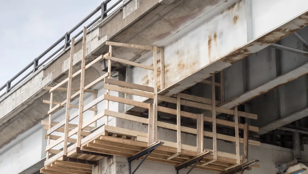
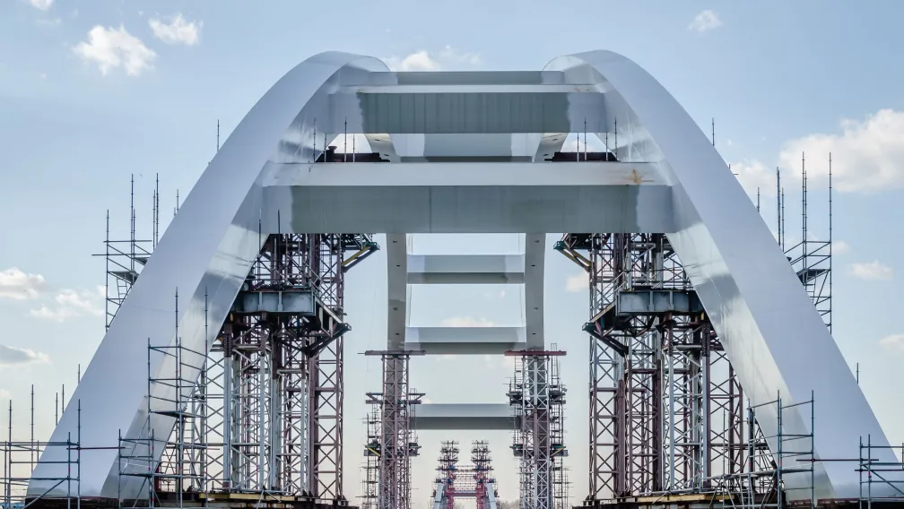
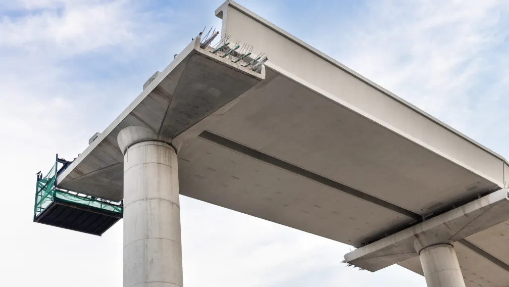
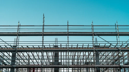
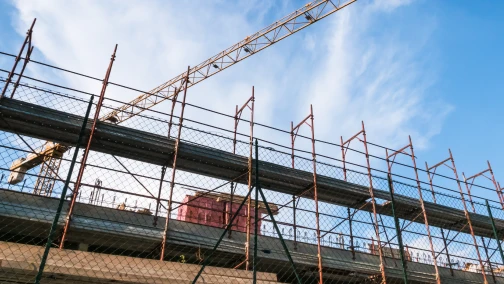
Executing maintenance, retrofitting, or expansion works on highway and railway overpasses presents a distinct logistical constraint: the traffic flowing beneath the structure cannot be halted. Traditional ground-supported scaffolding is mathematically and legally impossible in these environments due to strict vertical clearance regulations and the imminent hazard of vehicle collisions. To bypass the airspace below, structural engineers deploy heavy-duty suspended and cantilevered scaffolding systems that anchor directly to the existing bridge deck or girders.
Designing an overpass staging system introduces extreme structural dynamics absent in standard commercial high-rises. Bridge scaffolds endure relentless low-frequency vibrations from heavy freight trains, aerodynamic wind-tunnel effects channeled under the deck, and massive eccentric bending moments. This technical guide examines the structural mechanics of bridge cantilever scaffolding, detailing the critical load transfer protocols, dynamic vibration fatigue management, and the exacting procurement standards required for the primary anchoring components that keep suspended staging systems safely aloft.
Direct Answer: What is a bridge cantilever scaffolding system?
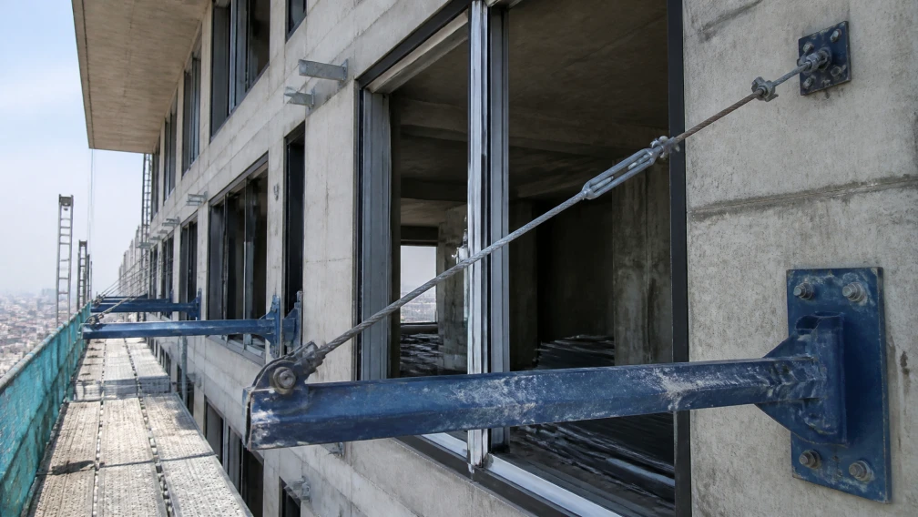
A bridge cantilever scaffolding system is a temporary suspended framework engineered to provide structural access to the underside or outer edges of an overpass without requiring ground support. The system utilizes heavy structural steel profiles projecting outward from the bridge deck edge. The overturning moment generated by the suspended working platform is counteracted by anchoring the inboard tail of the beam to the concrete deck, or by clamping it directly to the primary steel girders. These systems rely heavily on diagonal tension tie-rods and specialized anchoring nodes to maintain absolute rigidity against dead weights, lateral wind loads, and continuous dynamic traffic vibrations, allowing continuous structural maintenance while preserving the active traffic clearance below.
Overpass Staging: Unique Engineering Challenges
Unlike a static concrete building slab, a live highway or railway bridge is a kinetic structure. A fully loaded freight train or a convoy of commercial trucks induces massive rolling loads that cause the entire bridge deck to deflect downward and rebound within seconds. This continuous macro-deflection transfers severe low-frequency vibrations directly into the temporary scaffolding network anchored to it.
Furthermore, bridges crossing deep valleys or multi-lane interstate highways are subject to complex aerodynamic forces. The geometric span of the bridge acts as a roof, accelerating wind speeds beneath the deck through the venturi effect. The temporary suspended scaffolding must be engineered to resist immense uplift forces and lateral buffeting. If the anchoring system lacks multi-axial rigidity, these combined dynamic vibrations and wind loads will rapidly fatigue the mechanical fasteners, causing bolts to back out, welds to micro-crack, and friction clamps to gradually slip along the steel girders.
The Core Foundation: The Cantilever I-Beam
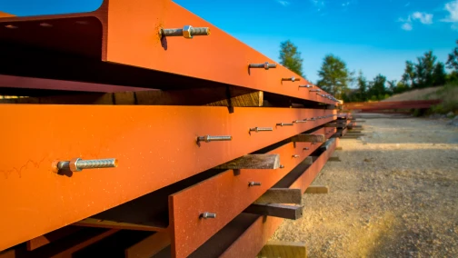
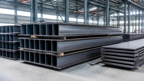
The entire structural integrity of an overpass staging system rests on the primary outriggers projecting from the bridge. Due to the extreme eccentric loads generated by drop-scaffolds suspended over open airspace, standard scaffolding tubes offer insufficient bending resistance. Structural engineers mandate the deployment of heavy-duty cantilever I-beams or H-section profiles to serve as the root foundation.
The selection of the I-beam is dictated by its Section Modulus (the geometric capacity to resist bending) and its metallurgical yield strength. For bridge applications, beams rolled from Q355B low-alloy high-strength steel (minimum yield strength of 355 MPa) are the universal standard. When positioned on the concrete deck edge, the beam acts as a lever. The extreme downward force of the suspended platform attempts to bend the beam over the concrete fulcrum while simultaneously attempting to rip the inboard tail upward. The wide flanges of the cantilever I-beam provide the necessary mass to resist localized web crippling at the fulcrum point, ensuring the structural steel does not crush under the concentrated reaction force.
Managing Diagonal Tension: The Twin-Ear Anchor Node
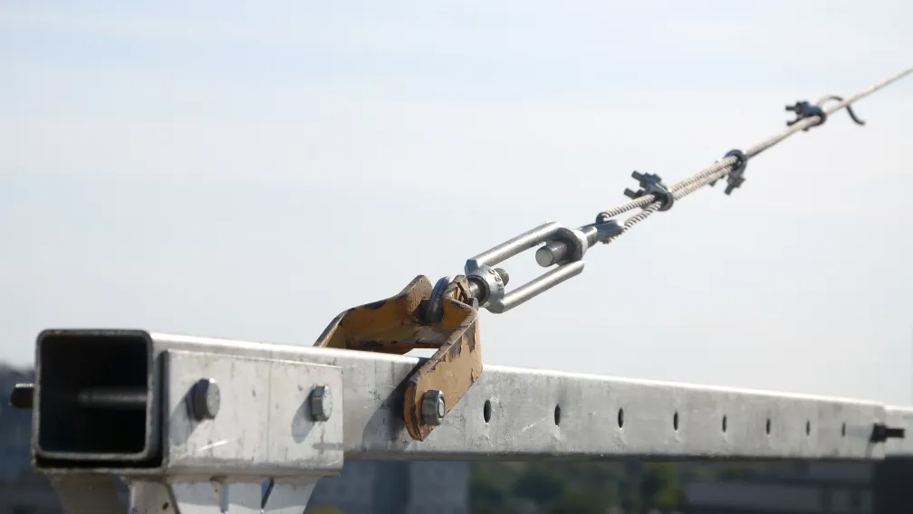
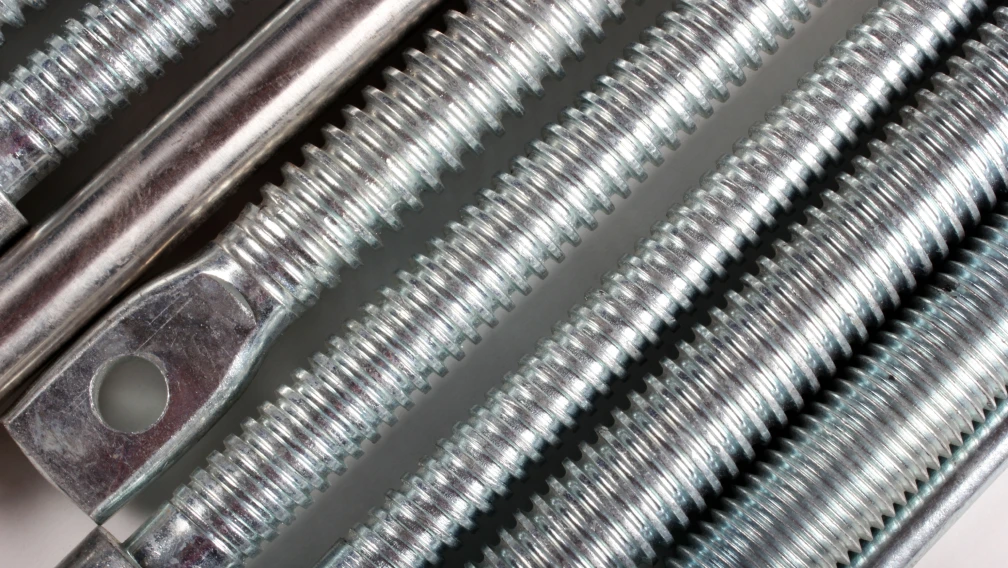
To comply with stringent deflection limits (often restricted to L/300 for bridge works) and to neutralize the massive bending moments on the projecting I-beam, structural designs invariably incorporate diagonal tension systems. High-tensile tie-rods connect the outermost tip of the projecting beam back to a higher anchoring point on the bridge parapet or deck.
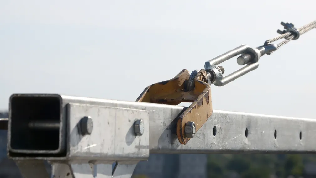
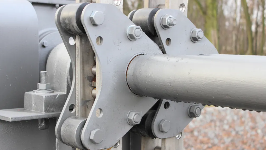
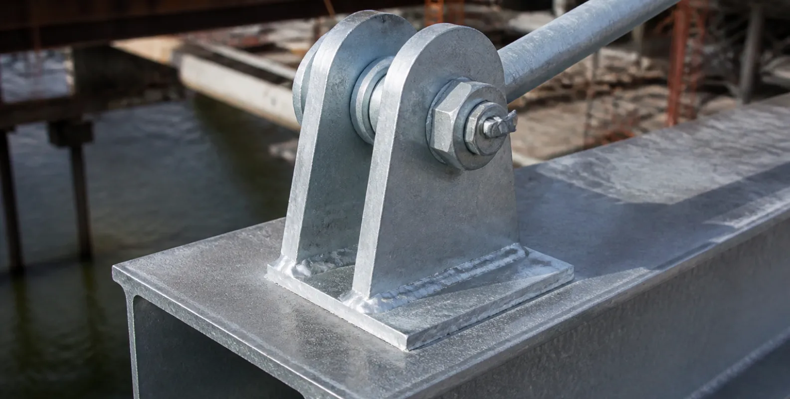
This diagonal tension must be transferred flawlessly into the steel beam without inducing eccentric, twisting stresses. This critical load transfer is executed using a twin-ear anchor. The twin-ear anchor is a heavy drop-forged or precision-welded steel bracket featuring two parallel vertical plates (ears) with aligned holes. It is welded directly to the top flange of the cantilever I-beam. A heavy-duty steel clevis pin passes through the twin ears and the eye of the tie-rod, creating an articulated joint.
The articulated nature of the twin-ear anchor is vital for bridge scaffolding. As the bridge vibrates and micro-deflects under traffic loads, the angle of the tie-rod shifts by fractions of a degree. A rigid, bolted connection would suffer catastrophic fatigue failure under these cyclic shifts. The clevis pin configuration allows the connection to pivot slightly, maintaining pure axial tension in the rod while safely dissipating the dynamic shockwaves generated by passing trains.
Anchoring Strategies for Concrete Box Girders
When deploying cantilever systems on post-tensioned concrete box girder bridges, the primary challenge is securing the inboard tail of the I-beam against violent rotational uplift. The preferred methodology involves pre-planning during the bridge construction phase by casting heavy-duty concrete threaded inserts directly into the deck slab.
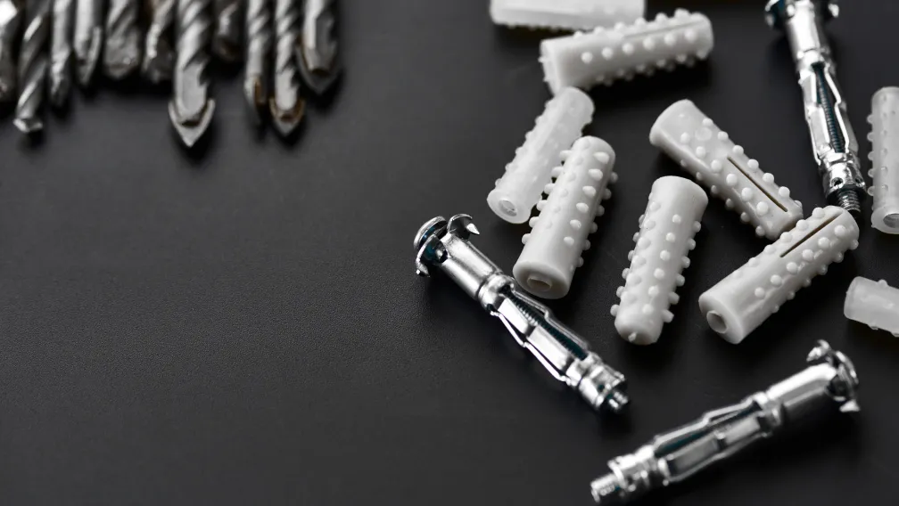
If the staging is a retrofit or maintenance operation, engineers must utilize post-installed heavy-duty chemical anchors. Mechanical expansion anchors are generally prohibited for the primary uplift restraints on bridge decks subject to heavy vibration, as the cyclic micro-movements can cause the expansion wedges to loosen over time. Chemical anchors (epoxy resins) bond chemically with the concrete pores, rendering them impervious to vibratory loosening. The base plates of the cantilever I-beams must feature widely spaced, longitudinally slotted holes. The slots accommodate the thermal expansion of the steel beam under direct sunlight, preventing the expanding steel from shearing the chemical anchors off at the concrete surface.
Anchoring Strategies for Steel Girder Overpasses
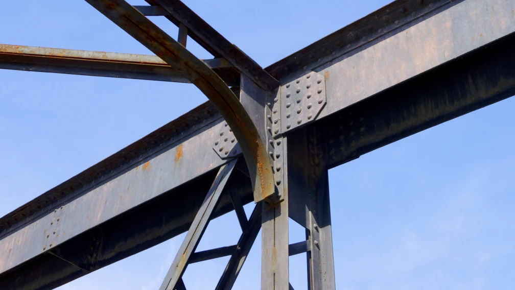
Bridges constructed with primary steel plate girders require an entirely different anchoring protocol. Drilling holes into the primary structural flanges of a bridge girder to bolt down scaffolding is strictly prohibited, as it creates stress risers that compromise the permanent integrity of the bridge.
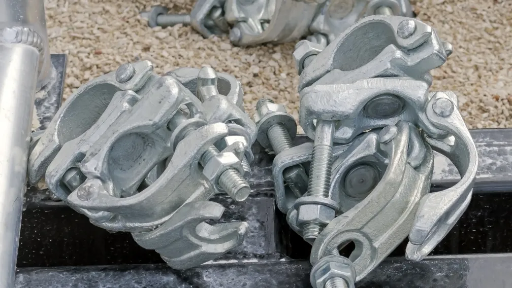
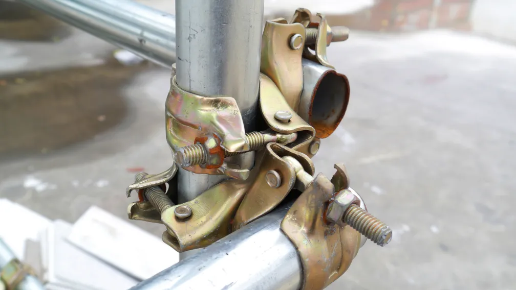
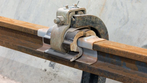
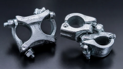
Instead, the cantilever I-beams are secured using engineered friction clamps (often referred to as beam clamps or girder couplers). These heavy drop-forged clamps grip the flanges of the bridge girder and the flanges of the temporary cantilever beam, locking them together through massive clamping torque. Because the system relies entirely on friction, the contact surfaces must be free of heavy rust scale or flaking paint. The clamping bolts are tightened to specific torque settings using calibrated wrenches. To counteract the micro-vibrations of traffic, these connections are frequently augmented with secondary safety chains or redundant locking nuts to guarantee the clamps cannot back off during the multi-month project lifecycle.
Dynamic Fatigue and Weld Inspection Protocols
The relentless cyclic loading on bridge scaffolding accelerates metal fatigue, specifically at the Heat-Affected Zones (HAZ) surrounding structural welds. When a twin-ear anchor is welded to a cantilever I-beam, the extreme heat of the welding arc alters the crystalline structure of the Q355B steel, making the immediate boundary layer brittle and susceptible to micro-cracking.
Under the continuous vibration of highway traffic, a microscopic lack-of-fusion defect can rapidly propagate into a full structural tear. Therefore, visual inspection of these welds is legally insufficient for bridge deployment. Procurement standards mandate that all primary load-path welds—especially those connecting the twin-ear anchors to the beam flanges—undergo Magnetic Particle Inspection (MPI) or Ultrasonic Testing (UT) before the equipment is permitted on site. Only welds achieving full penetration criteria (such as AWS D1.1 standards) can survive the kinetic environment of an active overpass.
Installation Sequence and Traffic Management
Erecting staging over active roadways requires military-level logistical precision. The installation sequence is strictly dictated by nighttime lane closures, often leaving crews with only four-hour operational windows.
- Pre-assembly: The cantilever I-beams, twin-ear anchors, and base plates are fully assembled, inspected, and torqued in the staging yard, minimizing active operations over the traffic lanes.
- Positioning: A mobile crane maneuvers the pre-assembled beam modules onto the bridge deck edge.
- Primary Anchoring: The inboard tails are immediately secured using pre-cured chemical anchors or heavy-duty girder clamps. Torque values are verified instantly by a Quality Assurance inspector.
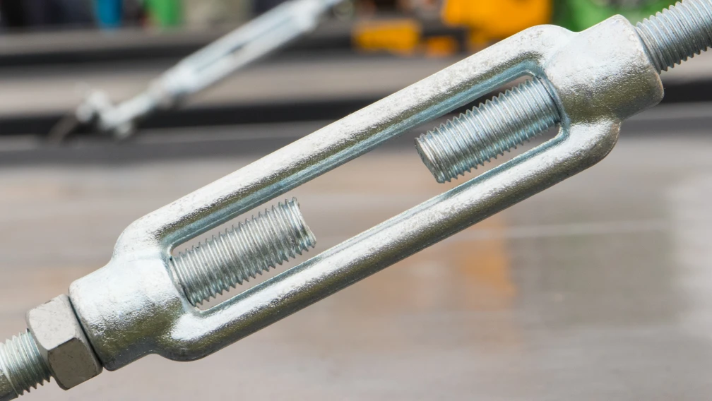
- Tie-Rod Engagement: The diagonal tie-rods are pinned to the twin-ear anchors and tensioned using closed-body turnbuckles. The tension is calibrated to introduce a slight upward camber to the beam, compensating for the anticipated deflection of the working platform.
- Decking Deployment: Once the primary structural steel skeleton is secured and rigid, the lightweight aluminum or steel decking is rolled out and locked into place, fully encapsulating the hazard zone below.
Procurement Verification Checklist for Bridge Scaffolding
The extreme liability associated with dropping materials onto a live highway demands zero-tolerance procurement protocols for bridge scaffolding components.
| Verification Metric | Required Documentation | Engineering Purpose |
|---|---|---|
| Steel Metallurgy | EN 10204 3.1 Mill Test Certificates | Verifies Q355B high-strength steel yield limits for cantilever beams. |
| Weld Integrity | NDT Reports (Ultrasonic or MPI) | Ensures twin-ear anchors lack internal voids susceptible to fatigue. |
| Coupler Slip Resistance | EN 74-1 Class B Test Certificates | Guarantees girder clamps sustain 25 kN slip loads under vibration. |
| Corrosion Protection | ISO 1461 Hot-Dip Galvanizing Report | Prevents thread seizure and rust fatigue during extended exterior deployment. |
| Traceability | Permanent embossed batch markings | Allows immediate on-site identification of load capacities. |
Working with Lengge's Engineering Division
Lengge specializes in the fabrication of heavy-duty structural steel components engineered specifically for the extreme demands of bridge, overpass, and viaduct construction. Our manufacturing bases produce fully certified cantilever I-beams, drop-forged girder clamps, and precision-welded twin-ear anchors designed to neutralize dynamic vibrations and massive bending moments.
Every structural component deployed for overpass staging undergoes rigorous, documented Non-Destructive Testing (NDT) to guarantee absolute weld integrity and metallurgical yield compliance before dispatch. To discuss the load parameters, wind shear requirements, and anchoring strategies for your upcoming highway or railway infrastructure project, submit your engineering drawings through our contact page. Our technical design team will return a customized structural supply proposal tailored to your specific site logistics.
-

Lengge
Cantilever Scaffolding System Manufacturer
Lengge is a China-based factory producing cantilever I-beams, tie rods, couplers, embedded parts and full scaffolding accessories. We supply contractors, wholesalers and rental companies in over 50 countries from our own production facility in Hebei.