LANGUAGE


The extreme hazard of unanchored vertical standards on steel beams
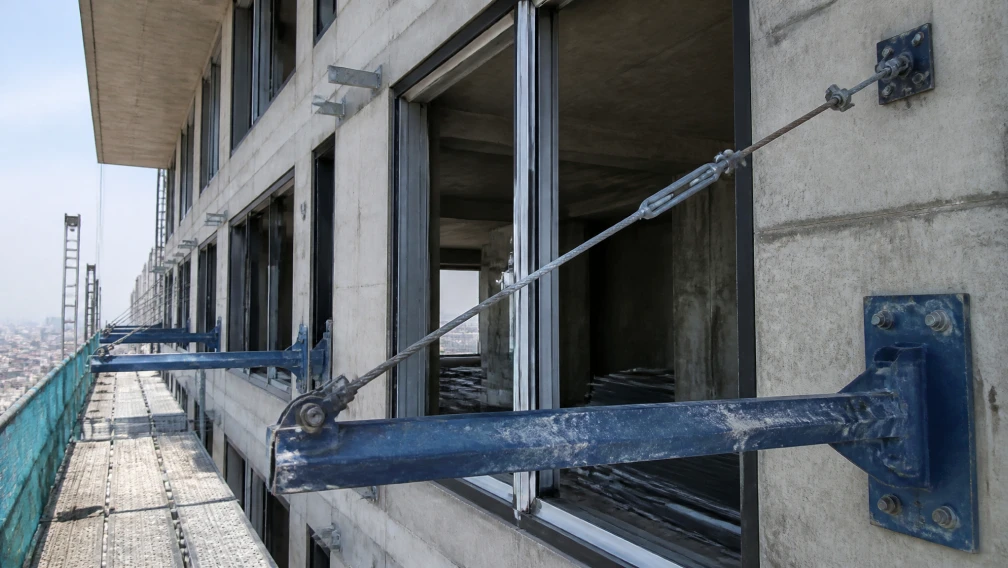
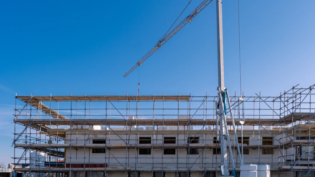
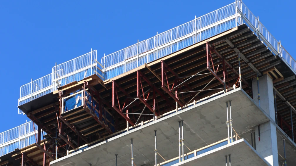
In the erection of high-rise cantilever staging systems, the entire multi-ton tubular scaffolding matrix rests upon horizontal structural steel outriggers. These outriggers, typically heavy-duty I-beams or H-beams, feature perfectly flat, smooth upper steel flanges. When site workers stand a vertical scaffolding standard (a 48.3mm steel tube) directly onto this flat steel flange, the coefficient of friction between the two smooth steel surfaces is nearly zero. Under a pure, static vertical load in a vacuum, the tube might remain stationary. However, active construction sites are highly dynamic environments.
High-altitude wind shear, the kinetic impact of laborers moving across the decking, and the vibration of tower cranes landing heavy pallets of masonry materials continuously subject the scaffolding network to lateral (horizontal) forces. Without mechanical fixation at the absolute base, these lateral forces will cause the vertical standards to slide horizontally along the smooth flange of the outrigger beam. If a standard slides off the edge of the beam, the vertical column loses its foundation, instantly triggering a progressive, catastrophic collapse of the entire exterior facade staging. To completely neutralize this lateral slip hazard, structural engineers mandate the factory integration of the scaffold positioning pin directly into the primary outrigger framework.
Direct Answer: What is a scaffold positioning pin?
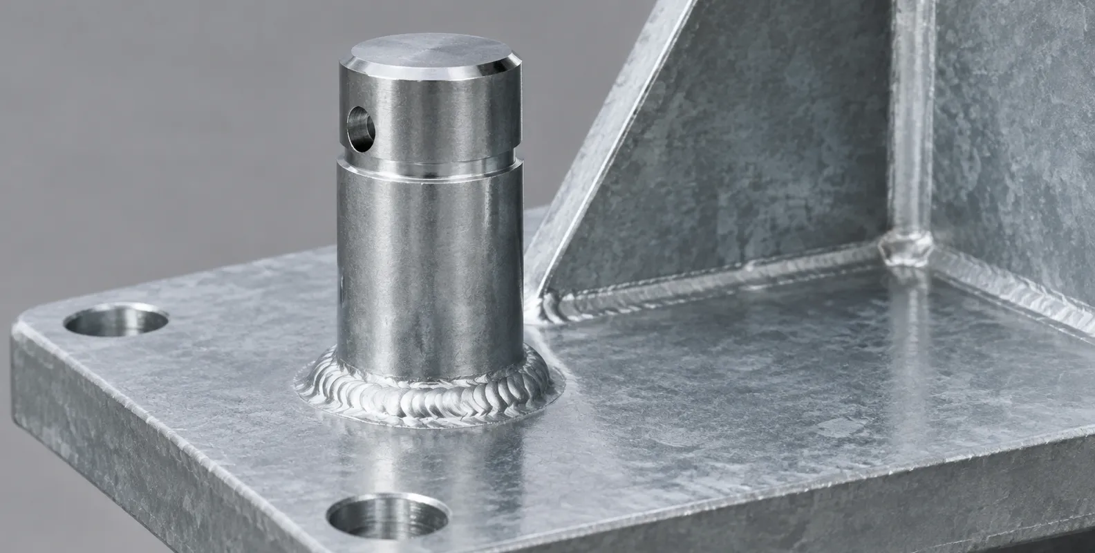
A scaffold positioning pin (often referred to as a base spigot or locating pin) is a solid, cylindrical steel dowel vertically welded to the top flange of a cantilever outrigger beam. It serves as the absolute foundational anchor point for the scaffolding matrix. The pin is precision-machined to an outer diameter slightly smaller than the internal diameter of a standard 48.3mm scaffolding tube. During erection, the hollow vertical standard slides directly over this protruding pin. The pin acts as an immovable mechanical shear dowel, physically locking the base coordinates of the vertical tube in place and providing total resistance against lateral displacement and horizontal sliding forces caused by wind shear or dynamic site vibrations.
Metallurgy: Solid round bar versus hollow pipe cutoffs
The manufacturing process and material selection of the positioning pin determine its ultimate shear capacity. Because the pin must resist the entire accumulated horizontal wind load acting against the scaffolding sail area, metallurgical integrity is non-negotiable. Budget fabrication shops often attempt to reduce raw material costs by utilizing short cutoffs of standard hollow scaffolding pipe (48.3mm OD) welded to the beam to act as the locating spigot. This is a severe engineering violation.
Hollow pipe possesses a thin wall section (typically 3.2mm or 4.0mm). When massive lateral forces push the vertical standard against a hollow pin, the thin walls of the pin act as a crumple zone. The hollow pipe crushes inward, deforming plastically until it shears off the base weld. Professional cantilever scaffolding systems rely exclusively on solid round steel bar for positioning pins. Machined from solid Q235B or Q355B carbon steel billets, these solid dowels present a massive cross-sectional area. A solid 36mm steel pin offers an exponential increase in shear resistance compared to a hollow tube, completely preventing crushing or snapping under extreme lateral impact loads.
Dimensional tolerances: Calculating the internal radial clearance
The operational success of a positioning pin relies on strict machining tolerances. The pin must allow the vertical scaffold tube to slide over it smoothly during manual erection, but it must not be so loose that it permits excessive kinetic slop. A standard heavy-duty scaffolding tube possesses an outer diameter of 48.3mm and a nominal wall thickness of 4.0mm. This yields a theoretical internal diameter (ID) of 40.3mm.
If a manufacturer machines the solid pin to a diameter of 40.0mm, the clearance is a mere 0.3mm. While mathematically viable on paper, this presents a nightmare on the jobsite. Galvanizing buildup, microscopic dents in the scaffold tube from previous rentals, or slight angular misalignment by the worker will cause the tube to jam instantly on the pin. Site laborers will be forced to sledgehammer the vertical standard into place, permanently damaging the steel. Conversely, a pin machined to 25mm leaves massive internal clearance. Every time the wind blows, the vertical standard will slam back and forth against the pin, generating kinetic shock loads that weaken the base weld. The engineering optimum for a 4.0mm wall tube is a positioning pin machined to an exact outer diameter of 36.0mm. This provides a total diametrical clearance of 4.3mm (or a radial clearance of 2.15mm all around), allowing smooth, drop-in erection while maintaining tight structural alignment.
The physics of the welding node: AWS D1.1 specifications
The positioning pin does not function independently; its capacity is entirely dictated by the strength of the weld connecting it to the outrigger beam flange. The pin transfers immense lateral shear forces directly into the base beam. A weak weld will snap instantly under these loads. International structural manufacturing codes, such as AWS D1.1, govern the exact parameters of this critical joint.
The pin must be secured using a continuous, 360-degree fillet weld around its entire base circumference. The throat thickness of the weld must be mathematically proportioned to the diameter of the solid pin and the thickness of the beam flange. For a 36mm solid Q355B pin, a minimum 8mm or 10mm continuous fillet weld is mandatory. Certified fabrication facilities utilize robotic MIG (Metal Inert Gas) welding arms to execute this joint. Robotic welding ensures constant travel speed, precise voltage control, and perfect shielding gas coverage, eliminating the porous, inconsistent, or under-penetrated welds commonly associated with manual stick welding.
Managing the Heat-Affected Zone (HAZ) on the primary beam
Welding a solid steel pin to the top flange of a heavy-duty cantilever I-beam is a highly technical metallurgical process. The localized application of thousands of degrees of heat melts the steel, fusing the pin and the flange together. However, the rapid heating and subsequent rapid cooling cycle permanently alters the crystalline structure of the steel in the immediate surrounding area. This area is known as the Heat-Affected Zone (HAZ).
If the welding process inputs excessive heat, or if the thick Q355B steel beam cools too rapidly in a cold factory environment, the HAZ becomes highly brittle and susceptible to hydrogen-induced cracking. Under heavy dynamic loading, the flange itself can crack and peel away at the weld root. Professional steel manufacturers manage the HAZ by utilizing strict pre-heating protocols on thick structural flanges and ensuring controlled, gradual cooling in the fabrication environment. This restores the ductility of the steel surrounding the pin, ensuring the primary outrigger beam retains its full bending and tensile capacity.
Why field-welding positioning pins is a critical safety violation
A persistent and dangerous shortcut in the scaffolding industry involves purchasing raw, unmodified steel beams and instructing site laborers to field-weld the positioning pins onto the flanges after the beams are installed on the high-rise floor. This practice is universally condemned by structural engineers and safety auditors.
Field welding on an active construction site introduces uncontrollable variables that destroy weld integrity. High winds blow away the shielding gas during MIG or TIG welding, introducing atmospheric oxygen and nitrogen into the molten weld pool, which creates severe internal porosity (air bubbles) that shatter under shear load. Furthermore, site workers lack the precision jigs required to align the pins perfectly. If a pin is welded just two degrees off vertical plumb, the 6-meter scaffold tube erected over it will lean heavily, rendering the entire facade grid out of square. All positioning pins must be 100% factory pre-welded, quality-checked, and surface-treated before the equipment arrives at the loading dock.
Pin height specifications: Balancing leverage and erection ergonomics
The vertical height of the positioning pin determines how securely it holds the scaffold tube, but it also dictates the physical difficulty of erecting the scaffolding. If a pin is cut too short (e.g., 30mm high), a severe wind gust or a worker tripping against the base of the standard can generate enough leverage to physically pop the tube up and over the pin, causing a collapse.
Conversely, if the pin is cut too long (e.g., 300mm high), it creates a severe ergonomic hazard. Erection crews handle 6.0-meter or 6.4-meter steel tubes weighing over 25 kilograms. To install the standard, the workers must physically lift the entire 6-meter tube vertically into the air until the bottom clears the top of the pin, and then slide it down. A 300mm pin requires laborers to hoist heavy steel well above their shoulders, risking severe musculoskeletal injuries and increasing the likelihood of dropping the tube off the edge of the building. The engineering optimum established by international scaffolding guidelines dictates a pin height between 100mm and 150mm. This height provides immense mechanical purchase to prevent tube pop-off while remaining low enough for safe, ergonomic manual handling during the chaotic erection phase.
Internal moisture management and preventing standard tube corrosion
A critical, often-overlooked consequence of placing a hollow tube over a solid welded pin involves water management. During the multi-year lifespan of a high-rise project, torrential rain constantly falls onto the scaffolding structure. The rain runs down the exterior and interior of the vertical standard tubes.
When the hollow tube sits flush against the flat flange of the outrigger beam, wrapping tightly around the solid positioning pin, a nearly watertight seal is created at the base. Rainwater traveling down the inside of the tube pools at the bottom, trapped against the flat steel flange with no avenue for drainage. Over months, this standing column of water silently corrodes the base of the vertical standard from the inside out, thinning the wall section exactly at the point of maximum compressive load. To combat this hidden danger, advanced positioning pins are not welded perfectly flush across their entire base. Manufacturers often utilize specialized grooved pins or integrate small drainage weep-holes into the weld profile, allowing internal condensation and rainwater to flow freely out of the tube base, thereby protecting the structural integrity of the scaffolding fleet.
Hot-Dip Galvanizing (HDG) challenges and dimensional buildup
Cantilever outrigger beams and their welded positioning pins must endure brutal atmospheric conditions. To prevent deep rust scaling, international tier-one contractors mandate Hot-Dip Galvanizing (HDG) for all primary structural components. The entire fabricated beam, complete with welded pins, is submerged in a 450°C bath of molten zinc.
The HDG process creates a thick, metallurgically bonded zinc-iron alloy coating, typically ranging from 80 to 100 microns thick. This heavy-duty coating presents a unique mechanical challenge for the positioning pins. The zinc bonds to all exposed surfaces, physically increasing the outer diameter of the solid steel pin by up to 0.2mm. Furthermore, as the beam is lifted out of the zinc bath, liquid zinc often runs down the pin and pools at the base weld, creating a thick, irregular metallic fillet. If the initial machining tolerance between the pin and the tube was too tight, this zinc buildup will make the pin completely unusable on site. Professional fabricators anticipate this zinc accumulation, intentionally machining the pins slightly undersized and utilizing post-galvanizing mechanical clearing (such as automated wire-brushing of the pin base) to guarantee flawless, drop-in tube fitment upon delivery.
The role of the positioning pin in establishing the orthogonal grid
The layout of a massive facade scaffolding network is not arbitrary; it must adhere to strict geometric grids to distribute loads evenly. The horizontal spacing between vertical standards (the bay length) is dictated by the length of the horizontal ledgers, typically 1.8 meters, 2.4 meters, or 3.0 meters.
The positioning pins welded to the cantilever beams act as the absolute starting coordinates for this entire three-dimensional grid. If the factory welds the pins to the beams at incorrect intervals, the error multiplies across the entire facade. For example, if the pins are welded 1.85 meters apart instead of exactly 1.80 meters, the standard horizontal ledgers will not reach between the vertical tubes. Workers will be forced to abandon the ledgers and cobble the structure together using overlapping tubes and swivel couplers, destroying the certified load capacity of the system. Procurement managers must demand precision CNC (Computer Numerical Control) layout and robotic welding to ensure the pins on the outrigger beams are spaced with millimeter-perfect accuracy, guaranteeing a seamless, rapid erection of the orthogonal scaffolding grid.
Defeating aerodynamic uplift: Why positioning pins do not resist tension
It is vital for structural engineers and site supervisors to understand the specific mechanical limitations of a positioning pin. A solid steel spigot welded to a flange provides massive, near-unbreakable resistance against lateral shear (horizontal sliding). However, it provides absolutely zero resistance against axial tension (vertical uplift).
During severe weather events, extreme wind gusts striking the debris netting act like a sail, generating massive aerodynamic lift. This uplift force attempts to physically pull the entire scaffolding structure upward, away from the building. Because the vertical standard simply rests loosely over the positioning pin, an upward wind gust will lift the tube straight off the pin, causing a catastrophic detachment. Therefore, the positioning pin must never be treated as an anti-uplift anchor. To counteract wind uplift, site engineers must utilize heavy-duty scaffold beam clamps or forged base-plate restraining couplers to physically lock the lowest horizontal ledgers directly to the flanges of the structural outrigger beams. The pin manages the shear; the clamps manage the tension.
Quality assurance: Magnetic Particle Inspection (MPI) for pin welds
Because the positioning pin is an absolute single point of failure for horizontal slip, the integrity of the fillet weld connecting it to the H-section steel beam must be verified before deployment. Visual inspection alone is grossly inadequate, as deadly micro-cracks often hide just beneath the surface of the weld bead.
Professional steel fabrication facilities utilize Magnetic Particle Inspection (MPI) to verify these critical nodes. An operative magnetizes the pin and the surrounding flange area, then applies a fine coating of iron oxide particles (either dry powder or in a liquid suspension). If a microscopic crack or lack-of-fusion defect exists in the weld, it disrupts the magnetic field, forcing the iron particles to gather directly over the invisible flaw, rendering it instantly visible under ultraviolet light. Procurement contracts for high-rise cantilever systems should explicitly demand MPI reports for all pin base welds, guaranteeing that zero defective components reach the active jobsite.
Fleet maintenance: Detecting bent pins and yield deformation
Cantilever outrigger beams are heavy capital assets designed to survive a decade of continuous rental cycles. However, the positioning pins welded to them are subjected to severe daily abuse. When tower cranes lower pallets of bricks onto the staging platform, accidental crane sway often causes the 2-ton load to slam laterally against the vertical scaffolding tubes. This kinetic impact transfers instantly into the positioning pin.
Over multiple projects, these repeated impacts can cause the solid steel pin to bend slightly out of plumb. Even a 3-degree bend in the pin will force the 6-meter scaffold tube to lean heavily, rendering the facade grid impossible to erect squarely. During the demobilization and turnaround phase at the scaffolding yard, maintenance crews must physically check every positioning pin using a specialized steel sleeve gauge and a machinist's square. If a pin exhibits plastic yield deformation (bending), it cannot be straightened with a sledgehammer, as cold-bending severely weakens the steel. The damaged pin must be cut off with a plasma torch, the flange ground perfectly smooth, and a brand-new solid pin robotically re-welded and re-galvanized before the beam returns to active inventory.
Integration with adjustable base jacks and leveling mechanisms
In standard ground-supported scaffolding, workers utilize threaded adjustable base jacks resting on timber sole boards to compensate for uneven terrain. When erecting on a cantilever steel outrigger, the paradigm shifts entirely. The top flange of the steel beam is already perfectly level and structurally rigid.
Therefore, utilizing threaded base jacks on top of an outrigger beam is redundant and introduces dangerous mechanical instability. A threaded base jack resting on a smooth steel flange has no way to grip the surface and will slide instantly under lateral load. The welded positioning pin replaces the base jack entirely. The vertical standard drops directly over the pin, resting its bare steel edge directly onto the flange of the outrigger beam. If minor height adjustments are required to compensate for specific architectural features, workers must make these adjustments higher up in the scaffolding matrix using adjustable U-head jacks at the top of the standards, maintaining the absolute rigid, pinned connection at the base.
B2B procurement mandates for international cantilever systems
Importing massive, pre-fabricated structural steel outriggers across international borders requires an uncompromising approach to supply chain verification. A base weld failure on a cantilever beam hanging 40 stories over a pedestrian zone carries catastrophic human and legal consequences. B2B procurement managers cannot risk selecting suppliers based solely on the lowest price per ton of steel.
To establish a secure, compliant supply chain, buyers must embed strict verification mandates directly into their commercial purchase agreements:
- Material Traceability: Demand official Mill Test Certificates (MTC) proving that the primary outrigger beams and the solid round bar used for the positioning pins are manufactured from verified Q355B (or S355JR) high-tensile carbon steel, explicitly rejecting mild Q235B substitutions.
- Welding NDT Reports: Require comprehensive Non-Destructive Testing reports (specifically Magnetic Particle Inspection or Ultrasonic testing) verifying 100% penetration and zero internal cracking on the fillet welds connecting the pins to the flanges.
- Dimensional Tolerance Guarantees: Specify the exact outer diameter of the pins (e.g., 36.0mm +/- 0.5mm) and mandate post-galvanizing inspection protocols to ensure zinc buildup does not render the pins too thick for standard 48.3mm tubes.
- Surface Finish Mandates: Explicitly specify heavy-duty hot-dip galvanizing (HDG) to a minimum of 80 microns for the entire outrigger assembly to guarantee survival in harsh maritime or aggressive industrial environments.
Logistics and grid arithmetic: Calculating pin and beam requirements
The logistics planning for a mega-facade project relies on precise area arithmetic driven by the scaffolding grid dimensions. Every single vertical standard resting on a cantilever beam requires exactly one positioning pin.
If the structural engineering plan dictates a heavy-duty loading bay requiring outrigger beams spaced every 1.2 meters, and the scaffolding matrix is three boards wide (requiring two rows of vertical standards), then each individual outrigger beam must be manufactured with exactly two positioning pins welded at the precise centerline distance of the transverse ledgers. A facade spanning 120 meters horizontally will require 100 outrigger beams, demanding a total of 200 perfectly aligned, robotically welded positioning pins just for the base level. Procurement officers must supply the manufacturer with the exact grid dimensions to ensure the CNC robotic welders place the pins flawlessly, as correcting misaligned pins on the jobsite is structurally and economically impossible.
Connect with our engineering team for certified outrigger systems
Lengge Steel manufactures certified, heavy-duty cantilever scaffolding systems for global high-rise logistics. Our production lines supply fully prefabricated Q355B cantilever I-beams, H-section outriggers, drop-forged anchors, and precision-machined solid steel positioning pins. We enforce strict robotic welding protocols, comprehensive NDT inspection, and premium hot-dip galvanizing to ensure flawless dimensional tolerances and massive shear capacity under extreme wind loads. Submit your building blueprints, target projection limits, and scaffolding grid dimensions to our engineering desk to receive a comprehensive structural quotation and certified manufacturing documentation. Visit our contact page to secure your high-performance facade access supply chain today.
Frequently Asked Questions
If a scaffolding standard is subjected to a 15 kN lateral wind load, what is the shear stress on a solid 36mm positioning pin?
To determine the shear stress, first calculate the cross-sectional area of the 36mm solid pin. The area ($A$) is calculated as $\pi \times r^2$, which equals $3.1415 \times (18\text{mm})^2 \approx 1017.8 \text{ mm}^2$. The shear stress ($\tau$) is the applied force divided by the area: $15,000 \text{ N} / 1017.8 \text{ mm}^2 = 14.73 \text{ MPa}$. A standard high-tensile Q355B solid steel pin possesses a minimum yield strength of 355 MPa. Therefore, a shear stress of 14.73 MPa is massively below the yield point, providing an immense structural safety factor against severe horizontal wind loads.
Why is it dangerous to use hollow scaffolding pipe cutoffs as positioning pins?
Hollow scaffolding pipes have thin walls (typically 3.2mm or 4.0mm). When massive lateral forces push the vertical standard against a hollow pin, the thin cross-section lacks the structural mass to resist the kinetic energy. The hollow pipe acts as a crumple zone; it crushes inward and deforms plastically before eventually shearing off at the base weld. Solid round steel bar must be utilized to provide exponential shear resistance and prevent crushing under heavy dynamic impacts.
What is the optimal outer diameter for a positioning pin used with a standard 48.3mm x 4.0mm scaffold tube?
A 48.3mm tube with a 4.0mm wall thickness possesses a theoretical internal diameter (ID) of 40.3mm. Machining a pin to exactly 40.0mm leaves only 0.3mm of clearance, guaranteeing the tube will jam due to minor dents or galvanizing buildup. The engineering optimum is an outer diameter of 36.0mm. This provides a total diametrical clearance of 4.3mm (a radial gap of 2.15mm all around), which perfectly balances smooth, rapid drop-in erection without permitting dangerous kinetic slop.
Why is field-welding positioning pins to outrigger beams strictly prohibited?
Field welding on an active construction site introduces severe, uncontrollable variables. High winds blow away the shielding gas, creating porous, air-filled welds that shatter under shear load. Site workers lack precision jigs, resulting in misaligned pins that force the vertical columns out of plumb. Furthermore, erratic cooling in cold environments creates brittle Heat-Affected Zones (HAZ) on the beam flanges. All pins must be factory pre-welded using robotics, proper pre-heating, and non-destructive testing.
Do positioning pins prevent the scaffolding from lifting upward during a storm?
No, positioning pins provide absolutely zero resistance to axial tension or aerodynamic uplift. The hollow vertical tube simply rests loosely over the solid pin. If extreme wind shear creates aerodynamic lift, the tube will pull straight up and off the pin. To counteract uplift, site engineers must utilize heavy-duty scaffold beam clamps or bolted restraining plates to physically lock the lowest horizontal tubes directly to the flanges of the outrigger beams.
How does Hot-Dip Galvanizing (HDG) complicate the manufacturing of positioning pins?
The HDG process submerges the fabricated beam in molten zinc, creating an 80-micron thick, metallurgically bonded corrosion barrier. This zinc coats all surfaces, physically increasing the outer diameter of the positioning pin. Furthermore, liquid zinc often runs down the pin and pools at the base weld, creating a thick metallic fillet. Professional fabricators must machine the pins slightly undersized and utilize post-galvanizing mechanical clearing (like automated wire brushing) to ensure the zinc buildup does not prevent the scaffold tube from sliding over the pin on site.
Why shouldn't positioning pins be manufactured taller than 150mm?
Excessive pin height creates a severe ergonomic hazard during erection. Site crews manually maneuver 6.0-meter steel tubes weighing over 25 kilograms. To install the standard over a 300mm pin, the laborers must hoist the massive steel tube dangerously high above their shoulders to clear the top of the pin before sliding it down. A pin height between 100mm and 150mm provides immense mechanical leverage to prevent the tube from popping off, while remaining low enough for safe, efficient manual handling.
What is Magnetic Particle Inspection (MPI), and why is it used on pin welds?
MPI is a non-destructive testing method used to detect hidden micro-cracks or lack-of-fusion defects in steel welds. An operative magnetizes the weld area and applies fine iron oxide particles. Any microscopic crack disrupts the magnetic field, forcing the iron particles to gather exactly over the invisible flaw, revealing it instantly under UV light. Visual inspection alone cannot detect sub-surface weld defects, making MPI reporting a mandatory procurement requirement for critical shear nodes like positioning pins.
Why does water pool inside the vertical standards resting on positioning pins?
Rainwater routinely runs down the inside of hollow scaffolding tubes. When the tube rests entirely flush against the flat steel flange of the outrigger beam, wrapping tightly around the solid pin, it forms a nearly watertight seal. The trapped rainwater pools at the bottom of the tube, silently corroding the base of the standard from the inside out. Advanced positioning pins integrate small drainage weep-holes or grooves in the base weld profile to allow this internal condensation to drain safely away.
How do positioning pins dictate the accuracy of the entire scaffolding facade?
The horizontal spacing between vertical standards (bay length) is dictated by standard ledger lengths (e.g., 1.8m or 2.4m). The positioning pins welded to the cantilever beams establish the absolute starting coordinates for this grid. If the factory welds the pins even 20mm out of alignment, the rigid horizontal ledgers will not reach between the vertical tubes. This forces workers to abandon the fixed ledgers and cobble the structure together with overlapping tubes, destroying the certified load capacity of the grid.
-

Lengge
Cantilever Scaffolding System Manufacturer
Lengge is a China-based factory producing cantilever I-beams, tie rods, couplers, embedded parts and full scaffolding accessories. We supply contractors, wholesalers and rental companies in over 50 countries from our own production facility in Hebei.