LANGUAGE


The structural constraints driving cantilever staging
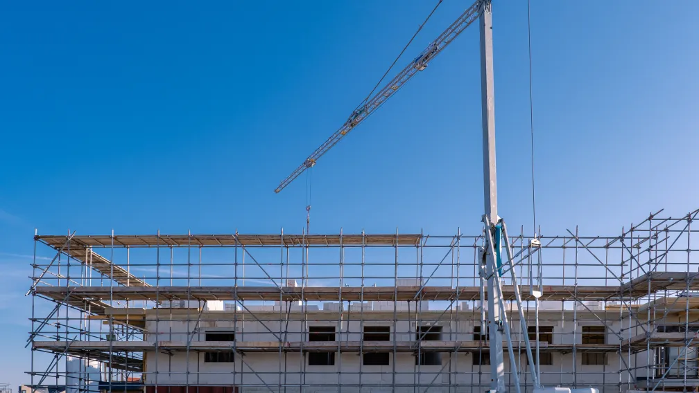
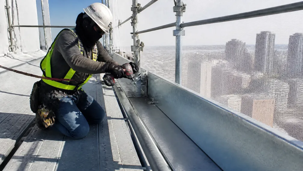
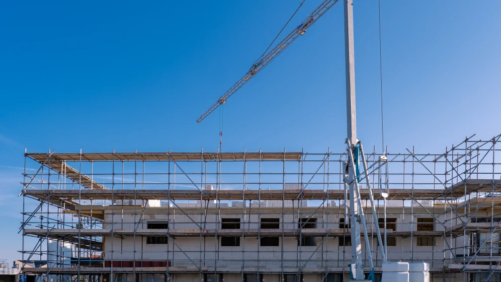
In mega-tower developments, high-rise commercial structures, and urban renovation projects, building temporary working platforms directly from the ground elevation is frequently impossible. Surrounding vehicular traffic, adjacent property lines, underground public utilities, and the sheer vertical height of modern skyscrapers render ground-supported scaffolding financially unviable and logistically prohibitive. Extending a continuous tubular steel matrix from the pavement to a 40th-floor working zone consumes massive steel tonnage, introduces extreme axial compression risks at the lower levels, and exceeds the maximum safe bearing capacity of standard base plates.
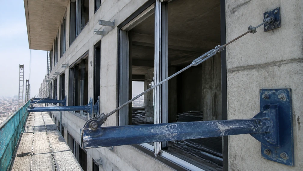
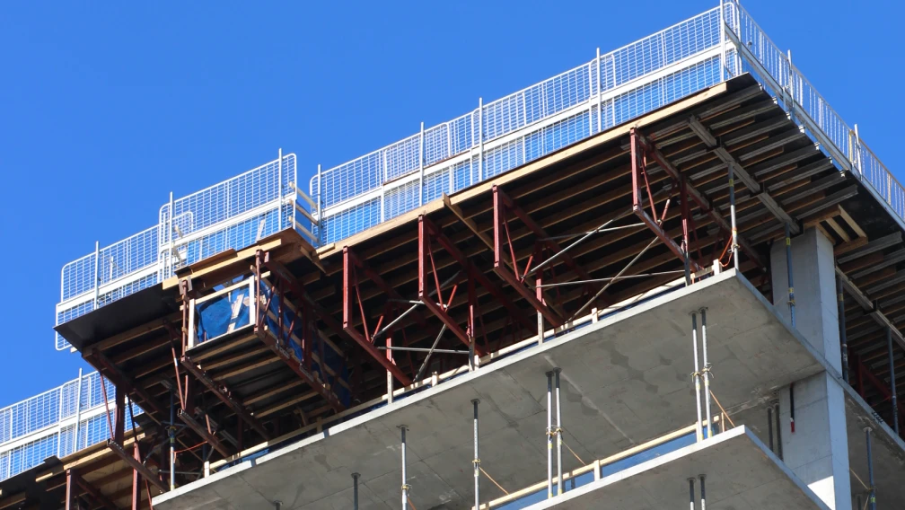
To bypass these ground-level restrictions, site engineers completely detach the temporary staging structure from the earth. They project horizontal steel outriggers directly from the intermediate floors of the active building. This engineering strategy transfers the entire dead weight and active live loads of the exterior working platforms directly into the permanent structural core of the building. This method drastically reduces steel consumption, opens ground-level access for heavy machinery, and accelerates construction timelines by localizing the temporary structures exactly where the active trades require access.
Direct Answer: What is a cantilever scaffolding system?
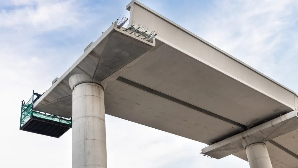
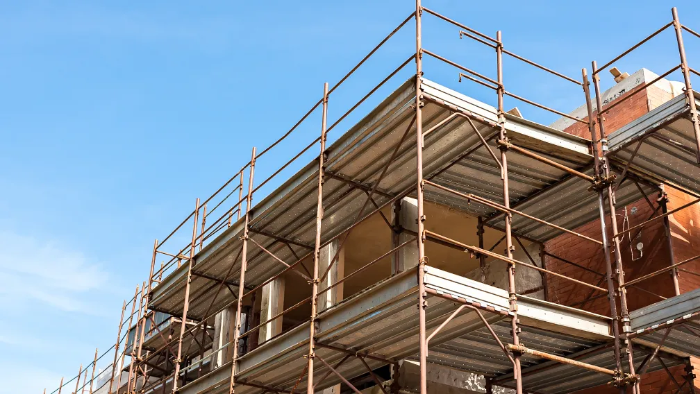
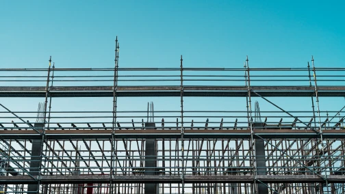
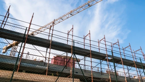
A cantilever scaffolding system is a specialized temporary staging structure that projects horizontally outward from the face of a building, completely unsupported from the ground below. It relies on a foundation of heavy-duty steel profiles (typically I-beams or H-beams) anchored securely to the interior concrete floor slab. The outboard projection of these beams serves as the structural base for erecting a standard vertical tube-and-coupler scaffolding matrix. To counteract the massive bending moments generated by the suspended exterior weight, the system utilizes diagonal high-tensile tie rods connected to the overhead concrete shear walls, converting downward bending forces into manageable diagonal tension and structural compression.
The physics of the fulcrum and bending moments
A cantilevered steel beam operates on fundamental mechanical lever principles. The edge of the concrete floor slab or the perimeter structural steel beam acts as the primary fulcrum. When laborers erect scaffolding tubes, lay timber decking, and deposit heavy masonry materials on the outboard section of the beam, gravity generates a massive rotational force known as a bending moment. This force attempts to push the outboard section downward while violently ripping the inboard tail section upward.
Managing this bending moment dictates the entire architecture of the cantilever system. Standard structural engineering practice attempts to mitigate this rotational force by keeping the external projection as short as possible while maximizing the internal anchoring support. However, in modern high-rise applications, deeply embedding the inboard tail disrupts interior finishing trades. Therefore, modern systems keep the inboard tail relatively short, relying instead on high-capacity diagonal tension members (tie-rods) attached to the extreme outer tip of the beam. This specific configuration neutralizes the bending moment directly at the source, transferring the load diagonally back into the building's concrete core and forcing the horizontal outrigger to act primarily in compression against the slab edge.
Selecting the primary horizontal outriggers: I-beams vs. H-section steel
The entire structural integrity of the staging network rests upon the primary horizontal outriggers. If these base beams yield, deform, or deflect excessively, the vertical scaffolding erected upon them will lean away from the facade, leading to catastrophic system collapse.
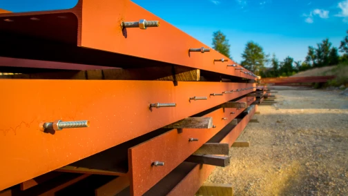
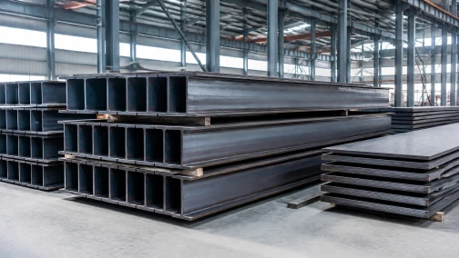
For standard mid-rise applications with limited outward projections, site engineers specify the cantilever I-beam, typically utilizing the standard 16# or 18# profiles. A 16# hot-rolled I-beam (160mm deep) provides a section modulus of 141 cm³, adequate for lightweight perimeter netting and worker access. The 18# profile (180mm deep) offers a section modulus of 178 cm³, absorbing a 26% higher bending load, making it the baseline for standard commercial bricklaying and concrete finishing.
However, when the scaffolding requires wide-span staging decks, massive material loading zones, or extreme outward projections exceeding 2.0 meters, the narrow flanges of standard I-beams become susceptible to lateral-torsional buckling under high wind shear. In these heavy-duty scenarios, engineers transition entirely to H-section steel. H-beams feature wide, parallel flanges and a more balanced web-to-flange thickness ratio. This geometry distributes the steel mass further from the neutral axis, providing immense rigidity against simultaneous vertical bending and lateral twisting forces.
Managing deflection limits: The L/250 mandate
A steel beam may possess the ultimate yield strength to hold a 5-ton load without snapping, but its behavior under that load is equally critical. Deflection refers to the physical downward bending of the beam tip under weight. If a cantilever outrigger deflects downward by 20mm, the vertical scaffold standard resting upon it will lean several degrees outward at the top of the 10-meter structure, tearing the wall ties out of the masonry.
International building codes (such as OSHA and EN standards) enforce strict deflection limits for temporary cantilever structures. The maximum allowable vertical displacement at the absolute tip of the outrigger is calculated as L/250, where L represents the length of the external projection. For a beam extending 1.5 meters into open space, the absolute maximum allowable downward deflection under peak intended working loads is 6 millimeters. Controlling this millimeter-scale deflection is the primary reason why simple cantilever beams are augmented with diagonal tension systems.
The critical role of diagonal tie-rods in load transfer
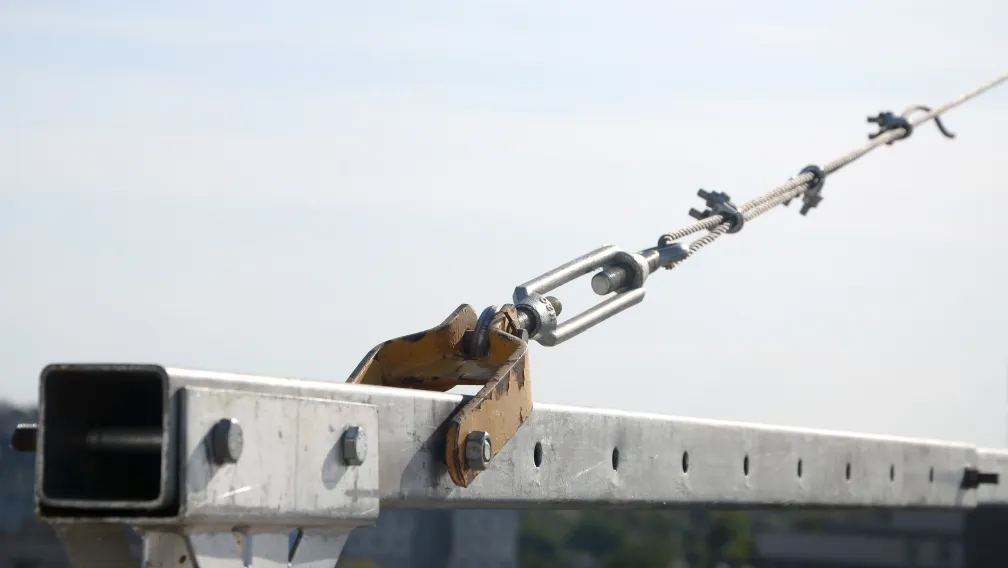
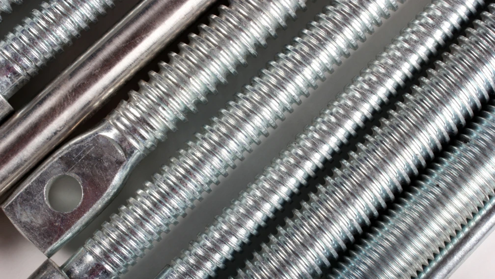
To eliminate tip deflection and bypass the need for massive, heavy steel profiles, modern cantilever systems employ a diagonal tension line. A high-strength scaffold tie rod is connected to the outer edge of the horizontal steel beam. This rod runs diagonally upward, anchoring securely to the concrete shear wall or the edge beam of the floor directly above the platform.
This configuration creates a highly rigid triangular truss. The downward force of the scaffolding platform attempts to push the beam down, but the diagonal tie-rod resists this motion, acting as a pure tension member. The angle of this tie-rod is strictly regulated. Engineering codes mandate that the angle between the diagonal tie-rod and the horizontal beam must never drop below 45 degrees. A steeper angle (e.g., 60 degrees) directs the majority of the force vertically into the concrete wall anchor. If the angle flattens below 45 degrees, the horizontal compressive force pushing back against the base beam increases exponentially, risking localized web buckling at the slab edge.
Specifying closed-body turnbuckles for tension adjustment
Connecting a rigid steel rod between two fixed points requires a mechanism to adjust its length precisely. If the tie-rod is too long, it hangs slack, providing zero support until the cantilever beam has already deflected past safe limits. If it is too short, the connection pin cannot be inserted.
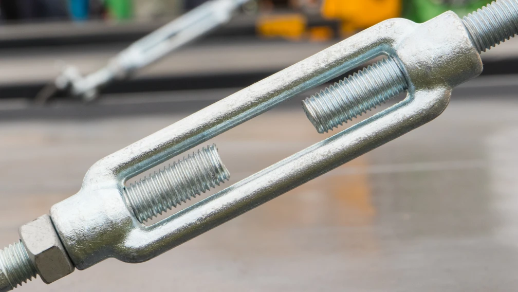
Site engineers integrate a closed-body turnbuckle directly into the tie-rod assembly. The turnbuckle features left-hand internal threads on one end and right-hand internal threads on the other. By rotating the central steel body using a spanner, the worker simultaneously draws both threaded rods inward. This action removes all physical slack and allows the worker to apply pre-calculated tension. The beam is slightly cambered (angled upward by 1 to 2 degrees) prior to erecting the scaffolding. Once the heavy scaffolding tubes and working materials are loaded, the beam settles perfectly level.
Procurement teams must explicitly specify closed-body designs. Open-body turnbuckles expose the internal threads. In high-rise environments, wet concrete splatter, abrasive mortar dust, and weather elements quickly foul exposed threads, causing them to jam permanently. The closed-body steel tube protects the mechanical threads, ensuring the turnbuckle remains fully adjustable throughout the multi-year project lifespan.
Twin-ear anchor integration at the beam and ceiling nodes
The mechanical capacity of the tension line is only as strong as its weakest connection node. Bolting a round tie-rod directly through a flat steel plate introduces severe eccentric bending stress at the bolt head, reducing the pure tensile capacity of the rod by up to 40%.
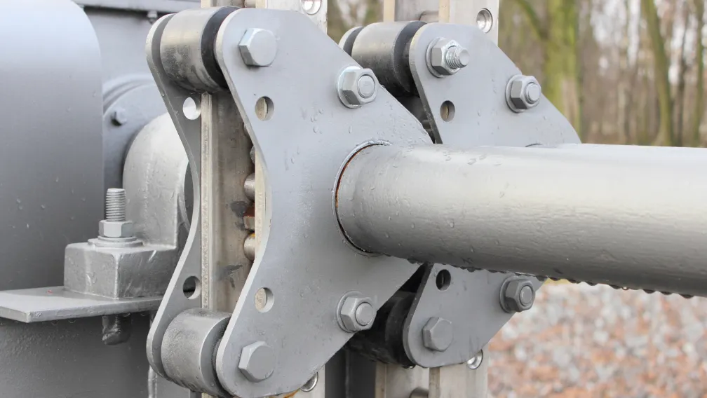
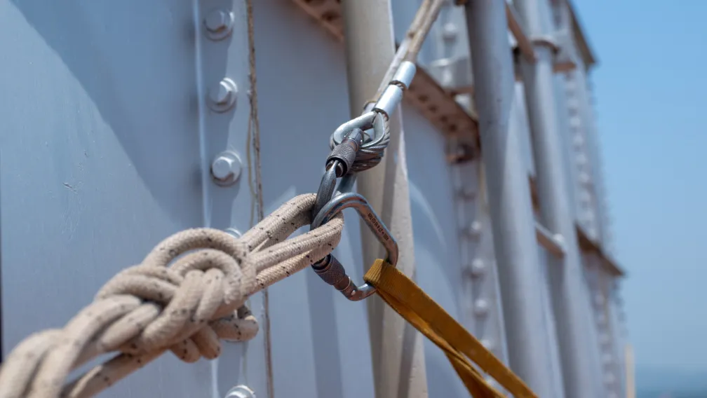
To create a flawless transfer of force, manufacturers utilize a heavy-duty twin-ear anchor. One anchor is fully welded to the top flange of the horizontal outrigger beam in the factory. A second twin-ear anchor is cast into the concrete wall or bolted to an embedded steel plate on the upper floor. The eyelet of the tie-rod fits perfectly between the two forged "ears" of the anchor, secured by a high-strength clevis pin and cotter pin. This clevis joint creates a pivoting hinge. The pivot ensures that regardless of the exact installation angle, the tie-rod remains in a straight, unbent line, transferring 100% of the platform's load as pure axial tension without inducing shear stress on the connection pins.
Concrete curing thresholds prior to load application
The entire cantilever structure ultimately relies on the compressive and tensile strength of the building's permanent concrete core. A critical scheduling hazard in high-rise construction occurs when contractors attempt to install outriggers and apply tie-rod tension to freshly poured floor slabs.
Wet or "green" concrete lacks the internal matrix to resist point loads. If a worker applies heavy tension to an upper wall anchor before the concrete cures, the anchor will rip completely out of the wall, causing a localized conical shear failure (concrete breakout). Structural engineering protocols mandate that the supporting concrete must achieve a minimum of 75% of its total 28-day design compressive strength before any mechanical load is applied to the embedded anchors or before the cantilever base beams are loaded with scaffolding weight. Pre-pour inspections and concrete cylinder crush tests are mandatory prerequisites before releasing the staging area for operational use.
Erecting the vertical tubular framework: Standards and ledgers
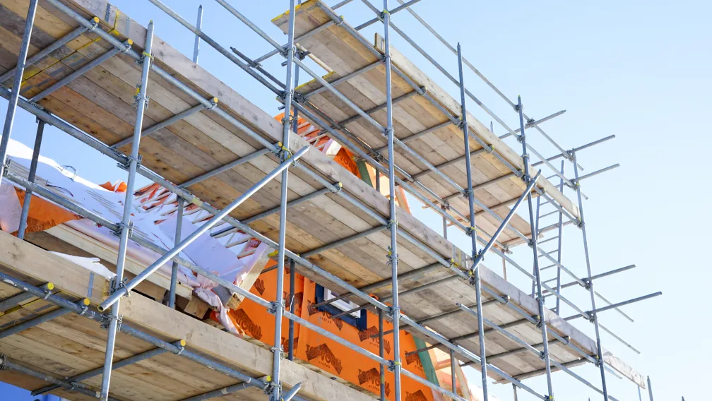
Once the horizontal steel outriggers are secured, leveled, and tensioned, the erection of the vertical scaffolding matrix commences. The structure utilizes standard 48.3mm outside diameter (OD) galvanized steel tubes with a standard wall thickness of 3.2mm or 4.0mm.
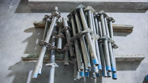
The vertical tubes (standards) transfer the gravity loads downward. The horizontal tubes (ledgers) tie the standards together, defining the lift heights and providing support for the decking transoms. The precision of this grid dictates its load-bearing capacity. To prevent the base of the vertical standards from sliding along the smooth steel flange of the outrigger beam, manufacturers pre-weld solid steel spigots (positioning pins) directly to the top flange. The hollow vertical scaffold tube slides directly over this spigot, physically locking the base coordinate in place and neutralizing horizontal slip forces caused by high winds.
Orthogonal locking mechanics using drop-forged double couplers
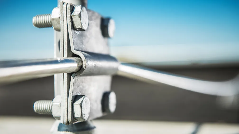
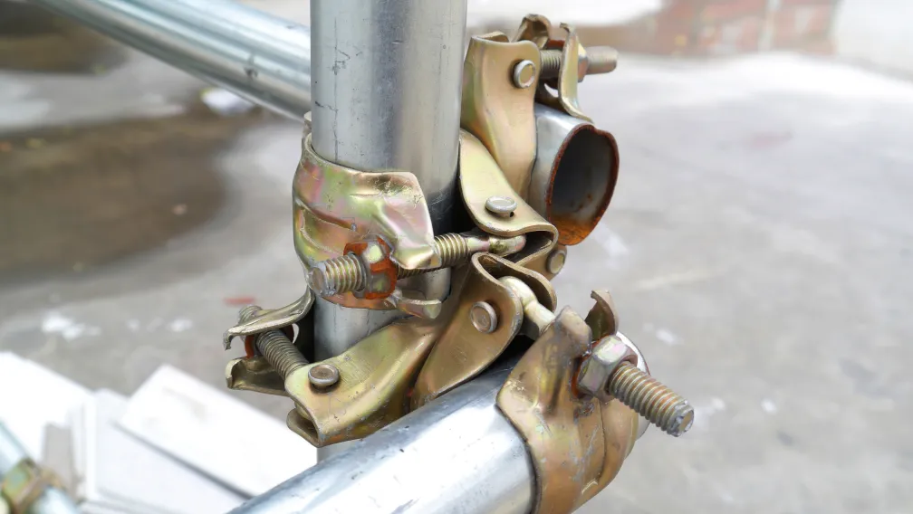
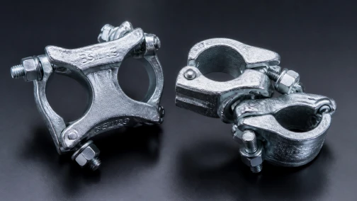
The intersection where a vertical standard meets a horizontal ledger represents the primary load-bearing node of the tubular framework. This connection must resist the downward sheer force of the platform weight attempting to slide the ledger down the standard. To secure this 90-degree intersection, laborers deploy heavy-duty scaffold double couplers.
These right-angle clamps rely entirely on high-clamping friction. Under EN 74-1 Class B specifications, a certified drop-forged double coupler tightened to 50 Nm of torque provides a slip resistance of 6.1 kN. The structural rigidity of the entire facade relies on drop-forged carbon steel components. Budget pressed-steel couplers deform under 50 Nm of torque, stretching the caps and instantly releasing the frictional grip on the tubes, leading to cascading node failures under heavy worker traffic.
Wind shear resistance and diagonal bracing using swivel couplers
A structure composed entirely of 90-degree orthogonal squares possesses virtually zero resistance to lateral twisting. High-altitude wind shear or asymmetrical loading on one side of the platform will cause the orthogonal grid to rack, sway, and eventually collapse like a house of cards.
Site engineers stabilize the matrix by installing continuous diagonal bracing tubes across the outer face and internal bays of the scaffold. Because these diagonal braces intersect the vertical standards and horizontal ledgers at unpredictable, non-90-degree angles, standard double couplers cannot be used. Erection crews utilize the scaffold swivel coupler. This drop-forged fitting features two rotating halves connected by a central heavy-duty rivet. It allows the clamps to secure two tubes at any arbitrary angle while providing a certified slip resistance of 9.1 kN per coupler, effectively locking the scaffolding into rigid, unyielding triangles that easily absorb extreme wind shear forces.
Connecting structural scaffolding to permanent steel via beam clamps
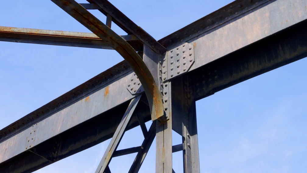
In certain scenarios, such as the initial base levels of a cantilever setup or during bridge deck maintenance, the tubular scaffolding must tie back directly into the permanent structural steel beams of the building rather than just resting on concrete. Welding temporary tubes to primary structural I-beams is strictly forbidden, as the extreme heat destroys the metallurgical temper of the structural steel. Drilling through the flanges weakens the beam's compressive strength.
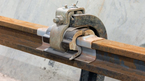
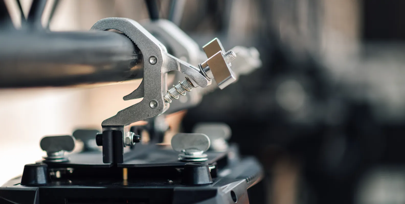
To create a secure, non-destructive mechanical link, contractors use a scaffold beam clamp (girder coupler). These heavy-duty forged fittings wrap over the flange of the structural steel beam and bolt tightly to a standard 48.3mm scaffold tube. They are always used in opposing pairs (one on the left flange, one on the right flange) to prevent eccentric rotational failure. This allows the scaffolding matrix to suspend from or anchor directly to the permanent steel skeleton without inflicting structural damage.
Decking security and aerodynamic uplift management
Once the tubular matrix is secured, workers lay timber or steel decking across the horizontal transoms to create the walking platform. High-rise environments introduce severe aerodynamic uplift. Wind striking the building facade accelerates, creating low-pressure zones that literally suck the boards upward off the transoms.
To prevent heavy timber boards from flipping and creating fatal drop hazards, every board is clamped mechanically to the support tubes. This is achieved using board retaining couplers. These low-profile steel brackets hook over the top edge of the timber board and bolt underneath the scaffold tube. They operate entirely as safety restraints. Unlike structural nodes that require 50 Nm of torque, board retaining couplers are tightened gently (20-30 Nm) to avoid crushing the cellular structure of the timber board while securing it permanently against hurricane-force uplift gusts.
Overcoming wall penetration defects: The zero-leakage approach
Legacy scaffolding systems often required workers to drill massive holes completely through the finished exterior masonry to bolt the cantilever beams into the floor slab. When the scaffold was dismantled, these gaping penetration points had to be manually patched with grout. Imperfect patching inevitably led to severe water leakage, compromising the building's thermal envelope and generating massive defect liabilities for the main contractor years later.
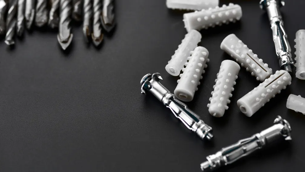
Modern cantilever engineering utilizes a zero-penetration approach. Heavy-duty threaded concrete inserts are cast directly into the concrete floor slab or edge beam during the initial pour. The cantilever outriggers bolt flush against the exterior face of the concrete, entirely eliminating through-wall drilling. When the project finishes and the beams are removed, the threaded holes are simply fitted with a permanent sealing cap or injected with waterproofing epoxy, guaranteeing the long-term weather integrity of the facade.
Corrosion protection: Hot-dip galvanizing for coastal and harsh environments
Cantilever outriggers, tie-rods, and turnbuckles are exposed to severe weathering for the entire duration of the high-rise project. Unprotected carbon steel oxidizes rapidly when subjected to coastal salt-fog, torrential rain, and the highly alkaline moisture of wet cement.
Deep rust scaling slowly consumes the base steel, reducing the wall thickness of the I-beams and compromising the thread integrity of the turnbuckles. Basic industrial paint or thin electro-zinc plating provides inadequate protection, scratching off rapidly during crane handling. International tier-one contractors specify Hot-Dip Galvanizing (HDG) for all primary structural components. Submerging the fabricated steel in molten zinc creates a thick (80 microns minimum), metallurgically bonded zinc-iron alloy coating. HDG withstands brutal mechanical abrasion and provides decades of total rust prevention, maximizing the equipment's lifespan across multiple rental cycles.
Pre-installation factory fabrication vs. field welding hazards
Attempting to fabricate a cantilever system on an active jobsite is a massive safety hazard and an economic drain. Procuring raw 6-meter steel beams and tasking workers to cut them to length, drill anchor holes with magnetic presses, and field-weld the twin-ear lugs introduces uncontrollable variables. Field welding under erratic weather conditions often leads to hydrogen embrittlement and poor penetration, causing lugs to snap off under tension.
Modern procurement strategies demand 100% factory pre-fabrication. The supplier cuts the I-beams to the exact architectural specifications, CNC-drills the heavy base plates, and robotically welds the anchor lugs and positioning pins. The entire assembly undergoes ultrasonic flaw detection in the factory before being hot-dip galvanized. This modular, bolt-together approach eliminates hazardous on-site hot-work, drastically accelerates erection timelines, and guarantees that every component meets its calculated Safe Working Load.
Static vs. dynamic loads: Worker traffic and material staging
Structural calculations for cantilever scaffolding must account for the difference between static dead weight and dynamic live loads. The dead weight consists of the steel tubes, the couplers, the decking boards, and the outrigger beams. This load is constant and easily calculated.
The live load involves workers, moving wheelbarrows, and the staging of heavy materials like pallets of bricks or buckets of mortar. When a crane drops a 1-ton pallet onto the staging deck, the sudden stopping of the load generates kinetic energy. This dynamic impact forces the scaffolding to absorb a momentary shock load significantly higher than the static weight of the pallet. Structural engineers apply a dynamic multiplier (typically 1.25 to 1.30) to all live load calculations. Site managers must strictly enforce the maximum permitted point loads, utilizing timber dunnage to spread the footprint of heavy materials across multiple transoms to prevent localized deck punching.
Safety inspection protocols: Torque wrenches and visual audits
A high-rise scaffolding network is not a static installation; it requires continuous maintenance. Vibrations from heavy machinery and thermal expansion and contraction cause bolted connections to loosen over time. Site safety officers execute strict, mandated inspection protocols (often governed by Scafftag systems) every 7 days and immediately following any severe weather event.
The inspection routine involves a visual audit of all cantilever base anchors, ensuring the turnbuckles have not unthreaded and the locking cotter pins remain securely through the clevis pins. Crucially, the inspector must utilize a calibrated torque wrench to physically test a random sample of double and swivel couplers across the grid. Any coupler testing below the required 50 Nm indicates a systemic failure in the erection protocol. The use of unregulated pneumatic impact wrenches during installation is strictly prohibited, as they routinely over-torque bolts past 100 Nm, permanently stretching the steel threads and inducing invisible micro-cracks in the forged caps.
B2B procurement specifications for global compliance
Importing massive quantities of structural scaffolding components requires uncompromising supply chain verification. A mechanical failure in a cantilever system hanging 50 stories above a public street carries catastrophic human and legal consequences. B2B procurement managers must embed strict verification mandates directly into their purchase contracts.
- Material Traceability: Demand Mill Test Certificates (MTC) proving the primary outrigger beams are rolled from Q355B (or equivalent S355JR) low-alloy high-strength steel.
- EN 74 Certification: Require official third-party laboratory destruction test reports verifying that all double and swivel couplers meet EN 74-1 Class B slip and tensile thresholds.
- Forging Verification: Ensure all couplers, twin-ear anchors, and turnbuckle bodies are manufactured from drop-forged carbon steel, rejecting any pressed-sheet or cast-iron substitutes.
- Surface Finish Mandates: Explicitly specify heavy-duty hot-dip galvanizing (minimum 80 microns) for all primary beams and tie-rod assemblies to guarantee survival in harsh maritime or industrial environments.
Connect with our engineering team for certified cantilever solutions
Lengge Steel manufactures certified, fully prefabricated cantilever scaffolding systems for global mega-projects. We supply Q355B heavy-duty I-beams, H-section outriggers, adjustable tie-rod assemblies, and a complete catalog of EN 74 drop-forged scaffolding couplers. Our production lines feature CNC precision drilling, robotic full-penetration welding, and premium hot-dip galvanizing designed for maximum rental longevity. Submit your building blueprints, outward projection limits, and target load capacities to our engineering desk to receive a comprehensive hardware schedule, structural FEA calculations, and a wholesale commercial quotation. Visit our contact page to secure your high-performance facade access supply chain today.
Frequently Asked Questions
Can I use standard 16# I-beams for a cantilever projection of 3.0 meters?
Calculations regarding the L/250 deflection limit dictate the answer. A 3.0-meter projection allows a maximum downward tip deflection of 12mm. A standard 16# I-beam lacks the section modulus (141 cm³) to resist the immense bending moment generated at a 3.0-meter distance under heavy working loads. It will deflect past safe limits and risk lateral-torsional buckling. For projections exceeding 2.0 meters, engineers must upgrade to heavier 18# profiles or Q355B H-section steel to maintain structural rigidity.
Why are closed-body turnbuckles mandatory for high-rise tie-rods?
In vertical construction, wet cement splatter, abrasive masonry dust, and heavy rain constantly fall onto the outrigger hardware. Open-body turnbuckles expose the delicate internal threads to this debris. The concrete hardens inside the threads, permanently jamming the turnbuckle and preventing future tension adjustments. A closed-body turnbuckle encases the threads inside a solid steel tube, shielding the mechanics and ensuring the tension line remains fully adjustable for the duration of the project.
What is the purpose of the twin-ear anchor on the cantilever beam?
The twin-ear anchor accepts the eyelet of the diagonal tie-rod and secures it with a clevis pin, creating a pivoting hinge joint. This pivot ensures that regardless of the specific installation angle of the tie-rod, the force is transferred perfectly as pure axial tension. Bolting a rod rigidly through a flat plate would introduce severe eccentric bending stress at the bolt head, reducing the rod's load capacity and risking sudden shear failure.
How long must I wait for concrete to cure before tensioning the upper tie-rod anchors?
Structural engineering standards require the concrete wall or edge beam to achieve a minimum of 75% of its total 28-day design compressive strength before applying mechanical loads. Tensioning a tie-rod against "green" (uncured) concrete will exceed the material's localized shear capacity, ripping the embedded anchor entirely out of the wall and triggering a localized conical breakout.
Why is drop-forged steel required for double and swivel scaffold couplers?
Drop-forging compresses heated steel billets inside high-tonnage dies, creating a dense, continuous grain structure that follows the physical contours of the clamp. This yields superior tensile strength, high ductility, and extreme resistance to dynamic impact cracking. Pressed sheet metal can stretch under 50 Nm of torque, and cast iron is brittle and shatters under shock loads. Only drop-forged steel safely handles heavy commercial scaffolding loads.
What happens if a worker uses a pneumatic impact wrench to tighten scaffolding couplers?
Pneumatic impact drivers easily deliver over 120 Nm of torque in seconds. The required specification for an EN 74 scaffold coupler is strictly 50 Nm. Applying 120 Nm stretches the Grade 8.8 T-bolt past its elastic yield point, permanently deforming the steel threads and inducing micro-fractures in the forged cap. The bolt loses its clamping elasticity and will likely snap under the next heavy dynamic load or thermal contraction cycle.
How do swivel couplers resist wind shear on a scaffolding facade?
A square framework of vertical standards and horizontal ledgers possesses minimal resistance to lateral twisting. Swivel couplers are used to attach diagonal scaffolding tubes across the facade. Because they rotate 360 degrees, they can secure tubes at any angle. These diagonal braces lock the square grids into rigid triangles, absorbing high-altitude wind shear and preventing the entire structure from racking or swaying out of plumb.
How does hot-dip galvanizing (HDG) differ from standard zinc plating?
Zinc plating (electro-galvanizing) applies a microscopic 10-micron layer of zinc, suitable only for dry, indoor aesthetics. It scratches off easily during transit. Hot-dip galvanizing submerges the heavy steel components in molten zinc, creating a thick (minimum 80 microns) metallurgically bonded zinc-iron alloy coating. HDG withstands brutal mechanical abrasion, coastal salt-fog, and highly alkaline wet cement, preventing deep rust scaling and extending the equipment's rental lifespan by decades.
Why are scaffold positioning pins welded to the top flange of the I-beams?
The flat, smooth steel flange of an I-beam offers zero frictional resistance to lateral movement. If a vertical scaffolding tube simply rests on the flange, heavy wind loads or worker movement will slide the base of the scaffold right off the beam. Factory-welded positioning pins (spigots) act as solid locators. The hollow vertical tube slides completely over the pin, mechanically locking the base coordinate in place and neutralizing all lateral slip forces.
What documents must procurement managers demand to verify Q355B steel quality?
To prevent fraudulent substitution of mild Q235B steel, buyers must demand official Mill Test Certificates (MTC) from the steel foundry. The MTC traces the specific heat number stamped on the beams and details the exact chemical composition (carbon, manganese, silicon ratios) and the physical mechanical test results (yield strength, tensile strength) to prove the material meets the 355 MPa minimum yield requirement for high-load cantilever applications.
-

Lengge
Cantilever Scaffolding System Manufacturer
Lengge is a China-based factory producing cantilever I-beams, tie rods, couplers, embedded parts and full scaffolding accessories. We supply contractors, wholesalers and rental companies in over 50 countries from our own production facility in Hebei.