LANGUAGE


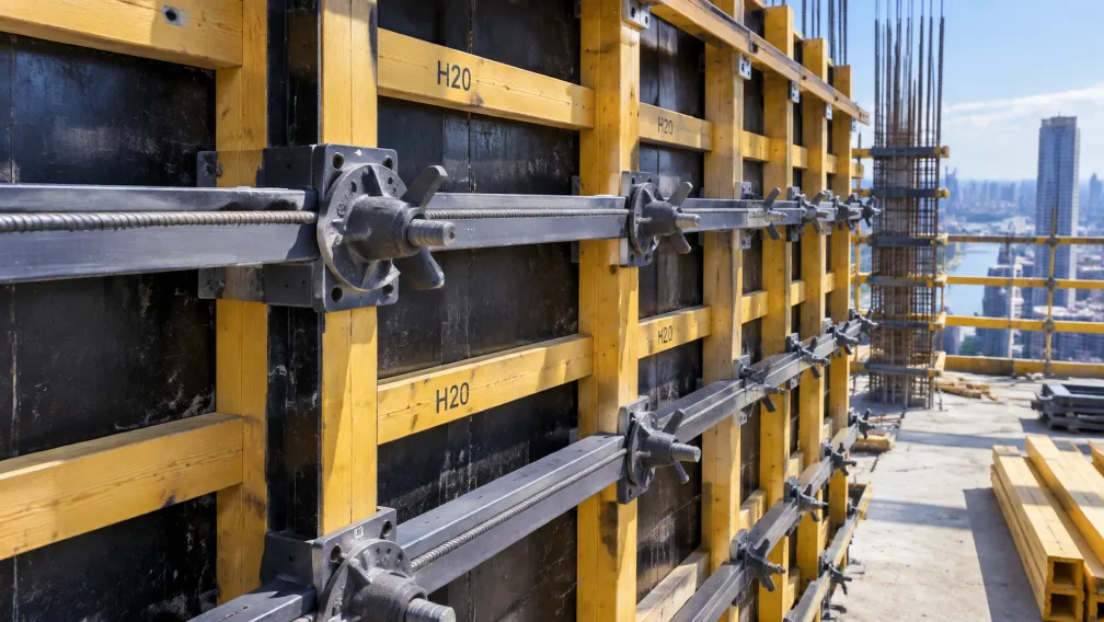
Fresh concrete is a liquid that weighs roughly two and a half tonnes per cubic meter, and formwork is the temporary vessel that holds it until it becomes structure. The tie system, running through the wall between the two formwork faces, carries the full hydrostatic pressure of that liquid for the hours between pour and set. The tie rod gets the engineering attention, but the connection hardware at each end, wing nut, washer plate, and fixing bolt, decides whether the rod's rated capacity reaches the joint. A formwork blowout investigation rarely ends at the rod; it ends at a wing nut that stripped, a washer that punched through, or a thread pairing that never matched.
This guide covers the four components of the formwork tie connection as one system: what each part does, how fresh concrete pressure translates into working loads per tie, which mechanical details separate rated hardware from look-alike stock, and what procurement should verify before the first pour depends on the delivery.
Direct Answer: What are formwork tie rod accessories?
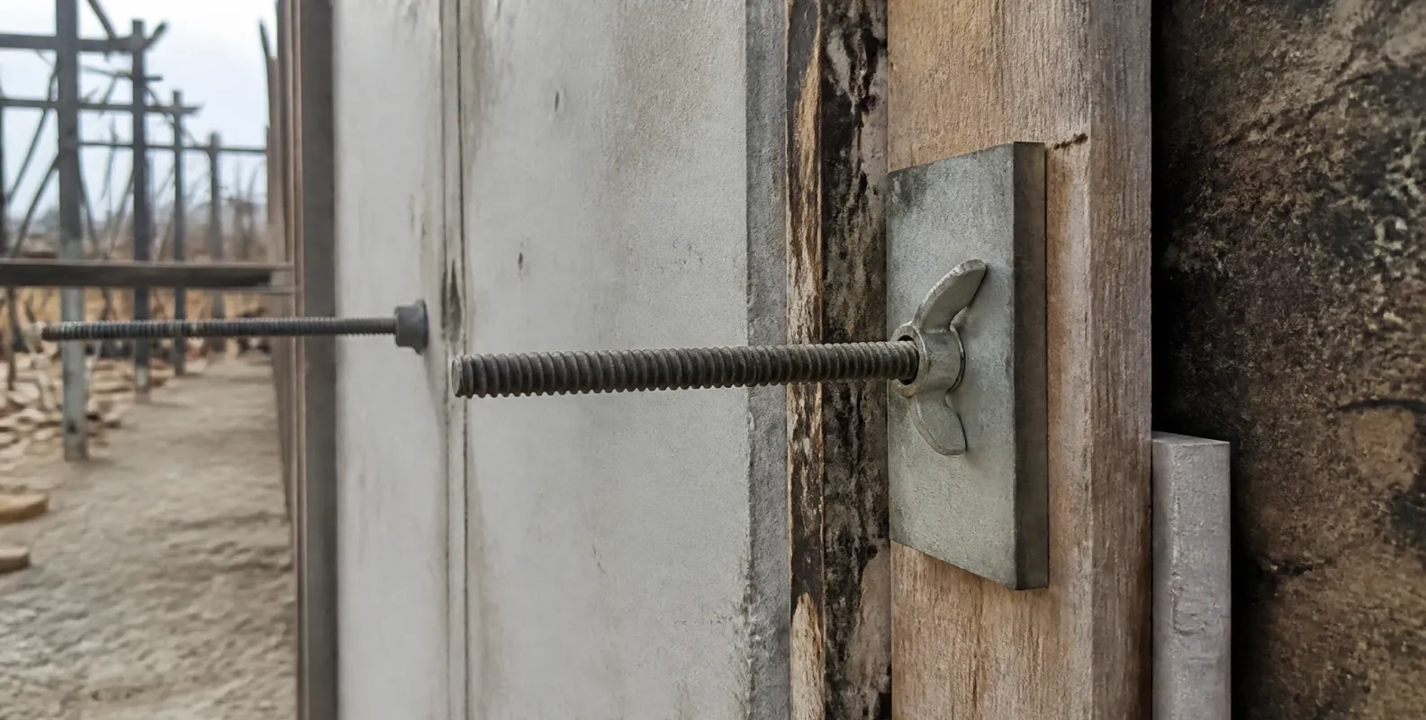
Formwork tie rod accessories are the connection components that complete a through-tie system in concrete formwork: the tie rod itself, a high-tensile threaded bar typically 15 or 17 mm in diameter that spans the wall; the wing nut, a forged nut with lever wings that clamps the formwork waling against the tie; the washer plate, a square plate behind the nut that spreads the clamping force into the timber or steel waling; and the installation bolt, which fixes embedded hardware such as concrete inserts to the formwork face before the pour. A standard 15 mm tie system works at rated loads around 90 kN, and every accessory in the chain is rated to match the rod.
Fresh concrete pressure: the load the accessories must hold
The design load on a tie connection comes from the lateral pressure of fresh concrete. In a wall poured at full fluid head, pressure at the base of the pour approximates concrete density times pour height: a 3-meter wall poured quickly generates pressures approaching 75 kN/m² at the base. Standards such as DIN 18218 refine the figure for pour rate, temperature, and consistency, but the practical order of magnitude stands: ties spaced on a typical 0.75 by 0.6 meter grid each see working loads of 30 to 40 kN at the base of a fast pour. That is the load arriving at each wing nut, and it arrives as vibration and impact while the poker works the concrete around the tie.
The four components and what each one does
Tie rod
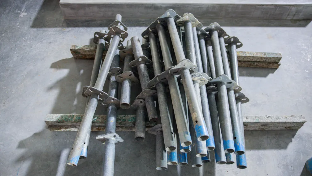
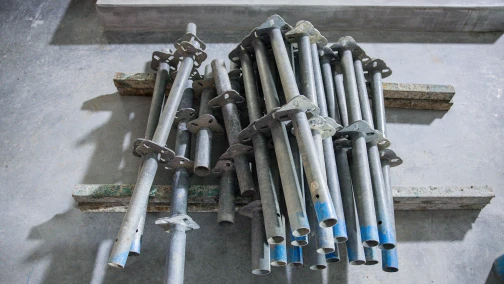
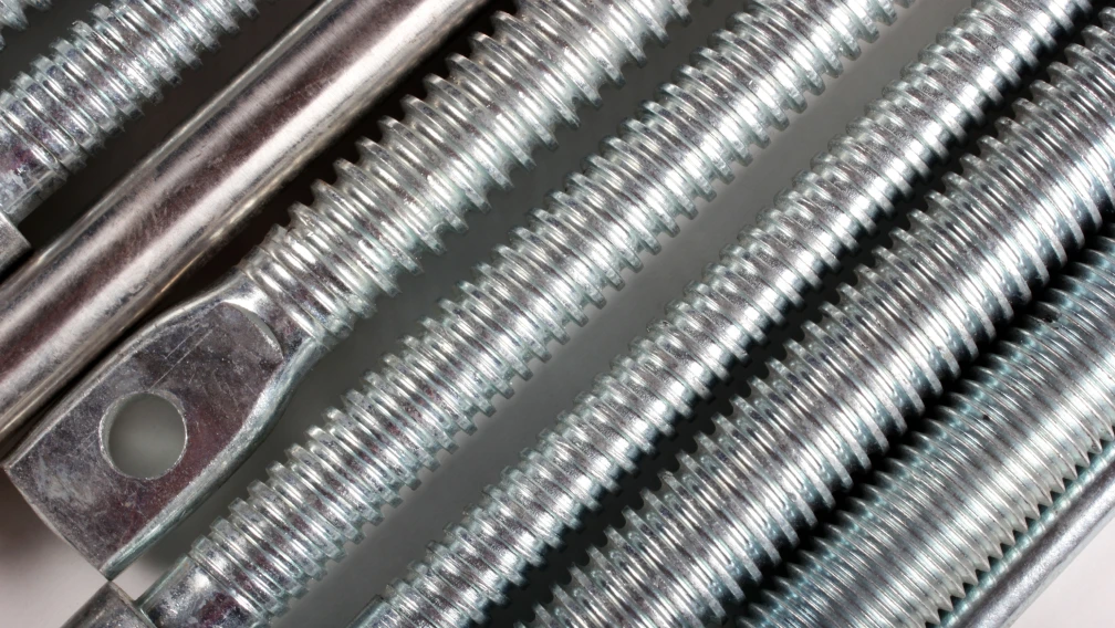
The scaffold tie rod is the tensile backbone of the system, a cold-rolled or high-tensile threaded bar that passes through the wall inside a spacer sleeve and anchors both formwork faces against each other. The 15/17 mm size dominates wall formwork with rated working loads near 90 kN. The rolled thread matters: a rolled thread displaces steel into the thread profile and keeps the core section intact, while a cut thread removes material and concentrates stress at the thread root.
Wing nut
The scaffold wing nut converts the rod's thread into a clamping force the erector can apply without a wrench, tightening by hand and seating with a hammer tap on the wings. The nut's capacity lives in its thread engagement length and the quality of its casting or forging. A wing nut with short engagement or a porous cast body strips under loads the rod would carry comfortably, and it fails suddenly, releasing the waling at full concrete pressure.
Washer plate
The flat washer plate sits between the wing nut and the waling, spreading the clamping force over enough timber or steel to prevent local crushing. Without the plate, the nut's contact ring drives into the waling, the clamp loosens as the timber crushes, and the form face drifts out of alignment during the pour. Plate thickness and size are specified against the waling material and the tie load, not chosen by habit.
Installation bolt
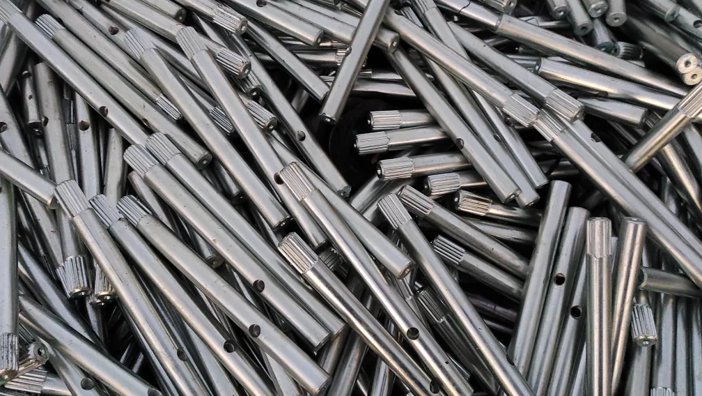
The formwork installation bolt works before the pour rather than during it, fixing embedded hardware such as concrete threaded inserts tight to the formwork face so the insert survives the pour in position with its thread sealed. The bolt withdraws at stripping and returns to service, so its thread and head must survive hundreds of cycles, which is why installation bolts are manufactured as reusable tools rather than consumed as fixings.
| Component | Function | Key specification | Typical failure if undersized |
|---|---|---|---|
| Tie rod 15/17 mm | Carries wall pressure in tension | Rolled thread, rated ≈90 kN | Tensile snap at thread root |
| Wing nut | Clamps waling to tie rod | Forged body, full thread engagement | Thread stripping at full pressure |
| Washer plate | Spreads clamping force | Size and thickness matched to waling | Punch-through, clamp loosening |
| Installation bolt | Fixes inserts to formwork face | Reusable grade, hardened thread | Insert displacement, thread seizure |
Mechanics of the clamped connection
The tie connection behaves as a preloaded joint. The wing nut, seated against the washer plate, tensions the tie rod slightly as it clamps the walings against the formwork face, and that preload keeps the joint closed when concrete pressure arrives. Three details govern whether the preload survives the pour. Thread match: the wing nut must be manufactured for the tie rod's thread profile, because tie rod threads are coarse trapezoidal forms, and a nut cut to a metric ISO thread will start on the rod and strip under load. Engagement length: the nut must run onto the rod by several full turns before tightening, or the engaged thread length falls below the stripping threshold. And seat condition: mud, concrete residue, or a twisted waling between plate and form face consumes the preload in settlement during the first minutes of the pour, which is when the pressure peaks.
Common field errors
Formwork failure reports repeat the same connection mistakes. Wing nuts mixed across suppliers, where thread profiles differ by fractions of a millimeter and engagement degrades with every reuse cycle. Missing washer plates on timber walings, replaced by nothing or by a standard flat washer sized for a bolt rather than a tie load. Tie rods welded to lengthen them or to fabricate anchors, a practice that destroys the steel's working properties at exactly the section under load; tie systems are never welded. And wing nuts tightened by hammering the wings until they bend, which over-tensions the rod into its plastic range and leaves the joint weaker than a hand-tight one. The corrective on all four is procedural: matched components, complete assemblies, and a torque discipline stated by the formwork designer.
Installation sequence for the tie connection
- Confirm the set. Verify rod, wing nuts, and washer plates are one matched system by thread profile and rating before the formwork closes.
- Position the sleeve. Fit the spacer sleeve and cones through the wall at the tie positions shown on the formwork drawing.
- Thread the rod. Pass the tie rod through the sleeve with equal projection at both faces, so both wing nuts engage their full thread length.
- Fit plate and nut. Seat the washer plate flat against the waling, run the wing nut on by hand for several turns, then seat it with a controlled hammer tap.
- Check the face. Confirm the form face alignment after all ties are clamped, because a tie tightened out of sequence pulls the face out of plane.
- Watch the first lift. During the first concrete lift, monitor ties at the base of the pour, where pressure peaks, for any nut movement or plate embedment.
Procurement verification checklist
- System ratings. Declared working loads stated for the complete tie set, rod, nut, and plate together, not for the rod alone.
- Thread documentation. Thread profile and pitch drawings for rod and wing nut, confirming matched manufacture.
- Material certificates. Mill certificates for rod steel and nut castings or forgings, traceable to the production batch.
- Proof testing. Tensile proof test reports on sample tie assemblies, loaded through the nut and plate as the site will load them.
- Reuse condition grading. A stated policy for thread wear limits and rejection criteria, since tie hardware is a circulating asset.
- Complete-set supply. Rods, wing nuts, washer plates, sleeves, and installation bolts delivered as coordinated sets with a single documentation package.
Working with Lengge
Lengge manufactures formwork tie systems and their full accessory chain, tie rods, wing nuts, washer plates, installation bolts, and matching concrete inserts, produced in our Hebei facility and supplied as matched, documented sets to contractors, formwork companies, and distributors in more than 50 countries. Mill certificates and proof test records accompany every batch.
Send your wall heights, pour rates, and tie grid through the contact page, and our team will return the tie system specification and quotation for your formwork cycle.
-

Lengge
Cantilever Scaffolding System Manufacturer
Lengge is a China-based factory producing cantilever I-beams, tie rods, couplers, embedded parts and full scaffolding accessories. We supply contractors, wholesalers and rental companies in over 50 countries from our own production facility in Hebei.