LANGUAGE


The baseline sections for modern scaffolding layouts
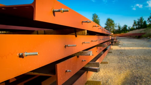
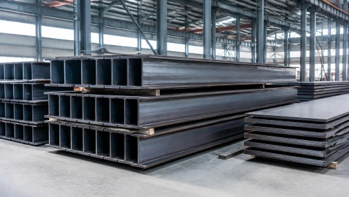
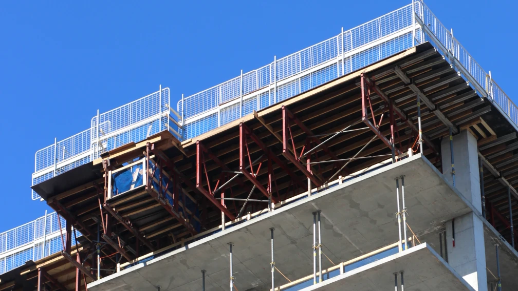
Structural engineers and scaffold designers consistently specify hot-rolled 16# and 18# profiles as the primary horizontal support members for high-rise cantilever scaffolding. These two profiles offer the optimal balance between load-bearing capacity, raw material cost, and manual handling weight on the jobsite. Understanding the precise mechanical differences, physical dimensions, and manufacturing tolerances between the 16# and 18# designations dictates the safety margins of the entire exterior staging structure.
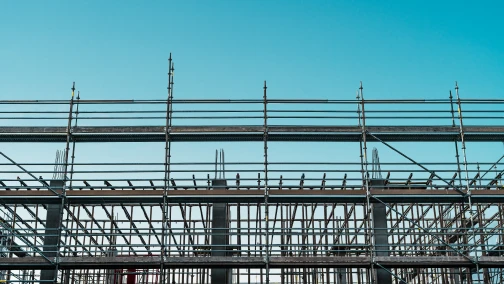
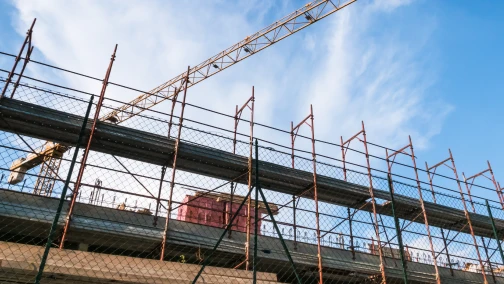
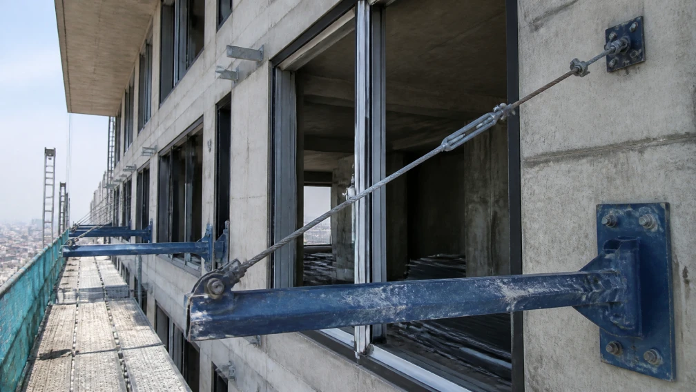
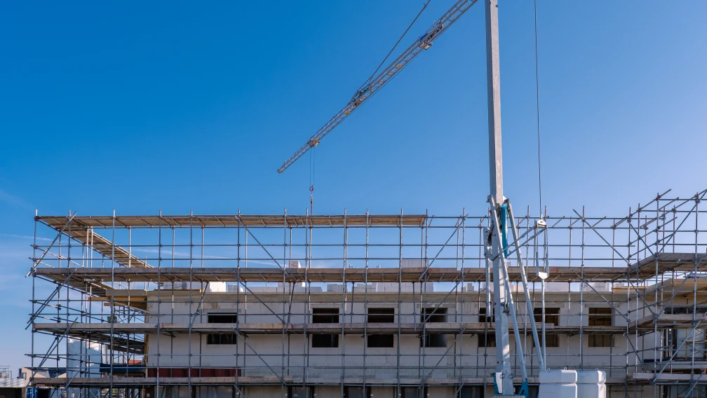
When a perimeter scaffold extends outward from a concrete floor slab, the entire dead load of the steel tubes, working platforms, and safety nets transfers directly into these horizontal outriggers. The beams must resist severe bending moments and downward deflection forces. The depth of the steel section directly dictates the moment of inertia, which determines how much weight the platform can support before the steel begins to bend past acceptable safety limits.
Direct Answer: What is the difference between 16# and 18# cantilever I-beams?
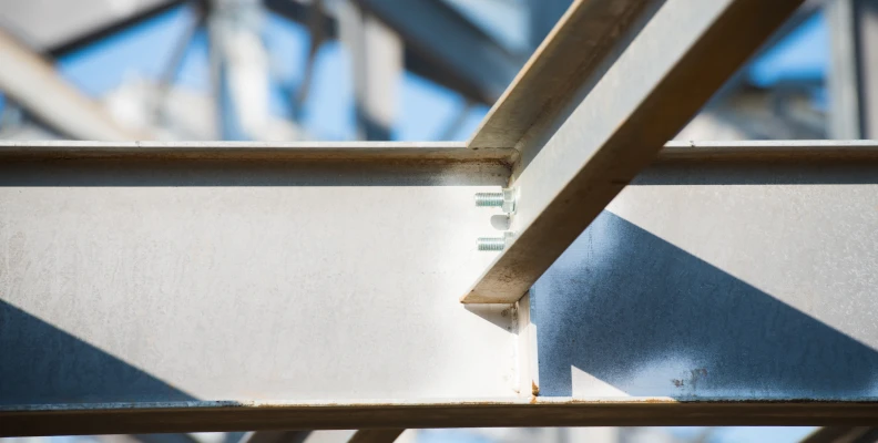
The primary difference lies in their physical depth, weight, and bending resistance. A standard 16# cantilever I-beam is 160mm deep, weighs 20.5 kg/m, and provides a section modulus (Wx) of 141 cm³. It is the baseline specification for standard perimeter scaffolding. An 18# cantilever I-beam is 180mm deep, weighs 24.1 kg/m, and provides a section modulus of 178 cm³. The 18# profile offers a 26% higher resistance to bending loads, making it the mandatory requirement for extended cantilever spans, heavy masonry zones, and geographical areas subject to extreme wind shear.
Mechanical properties and physical dimensions
Standardized steel production under international and Chinese domestic codes (such as GB/T 706) ensures that structural profiles maintain strict geometric proportions. The number designation directly correlates to the beam's depth in centimeters. A deeper beam places the mass of the horizontal flanges further away from the neutral axis, exponentially increasing the section's resistance to vertical deflection.
| Specification | 16# I-Beam | 18# I-Beam |
|---|---|---|
| Overall Depth (h) | 160 mm | 180 mm |
| Flange Width (b) | 88 mm | 94 mm |
| Web Thickness (tw) | 6.0 mm | 6.5 mm |
| Standard Weight | 20.5 kg/m | 24.1 kg/m |
| Section Modulus (Wx) | 141 cm³ | 178 cm³ |
| Moment of Inertia (Ix) | 1130 cm⁴ | 1660 cm⁴ |
Engineering procurement teams must match these static values against the anticipated working load limits of the scaffolding grid. The 16# I-beam serves adequately for standard residential facades where worker loads are light and standard tie-rod anchors provide close vertical support. However, commercial towers involving heavy concrete formwork storage, exterior glazing units, or wide-span loading decks demand the superior stiffness of the 18# profile. For exceptionally heavy point loads, site managers transition entirely from standard channels to heavy-duty H-section steel to prevent lateral-torsional buckling.
Understanding negative manufacturing tolerances
A critical factor in B2B steel procurement is the management of negative manufacturing tolerances. Hot-rolling mills globally operate with permitted geometric deviations. Under standard structural codes, a mill can legally produce a 16# I-beam with a web thickness slightly thinner than the nominal 6.0mm dimension and a flange slightly narrower than 88mm. This is industry standard practice.
However, extreme negative tolerance (sometimes called "minus tolerance" in export markets) occurs when unverified suppliers intentionally roll the steel well below acceptable engineering limits to save raw material weight while billing the buyer for theoretical standard weight. A beam rolled to a severe negative tolerance loses massive amounts of its section modulus. An under-sized 18# beam may actually perform mechanically closer to a standard 16# beam, resulting in dangerous on-site structural calculations. B2B buyers must specify "actual weight billing" or mandate strict negative tolerance limits (e.g., maximum -5%) in their purchasing contracts to ensure the cantilever I-beams delivered match the safety calculations of their high-rise project.
Deflection control limits in cantilever designs
Cantilever structures are governed by deflection limits rather than just ultimate yield strength. A steel beam may hold a heavy load without snapping, but if it bends downward too far, the entire vertical scaffold resting upon it will lean away from the building facade. This creates eccentric loading on the scaffold couplers and vertical tubes, leading to catastrophic system collapse.
International building codes (such as OSHA regulations and European EN standards) strictly limit the maximum allowable deflection at the tip of the cantilever. The standard rule enforces a maximum vertical displacement of L/250, where L is the projecting length of the beam into open space. For a beam extending 1.5 meters from the concrete slab, the tip cannot deflect downward more than 6 millimeters under maximum intended working loads.
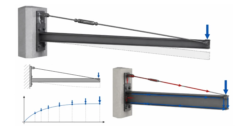
To control this deflection, site engineers keep the external projection as short as possible. They upgrade from 16# to 18# profiles when pushing the projection beyond 1.5 meters. Furthermore, they install diagonal high-tensile steel tie rods connecting the outer tip of the I-beam back up to the concrete wall, converting the bending stress into easily managed axial tension.
Factory pre-fabrication: Drilling and positioning pins
Raw steel beams require significant field modification before they can function as scaffolding supports. Procuring standard 6-meter raw I-beams and cutting them on-site generates massive labor costs, creates hazardous hot-work environments, and often results in misaligned anchor points. Modern B2B procurement focuses on fully prefabricated modular solutions.
Factory pre-fabrication involves cutting the beams to exact project lengths in a controlled environment. More importantly, manufacturers pre-drill the heavy base plates and the beam webs to accommodate standard embedded wall anchors or through-wall structural bolts. Field drilling an 18# I-beam with a magnetic drill press consumes excessive man-hours and tool consumables.
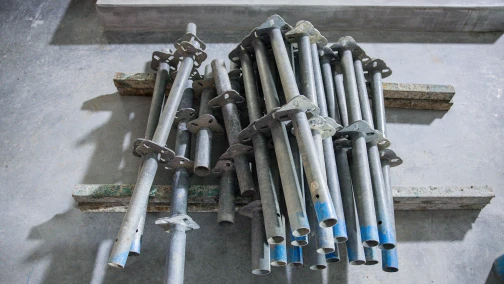
Additionally, factory welding of scaffold positioning pins directly onto the top flange of the I-beam ensures rapid site erection. These short, vertical steel pins act as locating spigots. The vertical scaffolding tubes slide directly over these pins, locking the base of the scaffold securely onto the steel beam and preventing any lateral slippage caused by high winds or worker movement.
Surface treatments for harsh construction environments
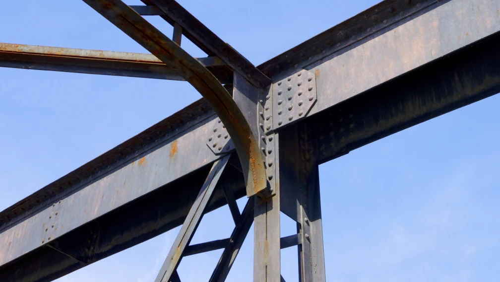
Cantilever outriggers operate exposed to severe weather elements throughout the construction cycle. Standard mill-finish steel oxidizes rapidly when exposed to rain, coastal salt fog, or the highly alkaline cement dust present on active jobsites. Deep surface rust reduces the structural thickness of the flanges over time, lowering the load capacity and rendering the beams unsafe for reuse on future projects.
Industrial painting offers basic protection but chips easily during manual handling and crane lifting. Hot-dip galvanizing (HDG) is the optimal specification for heavy-duty scaffolding components. The HDG process immerses the fabricated I-beam in a bath of molten zinc, creating a thick, metallurgically bonded alloy coating that resists severe mechanical impact. A minimum zinc coating thickness of 80 microns guarantees that the beams can endure multiple construction cycles across diverse climates without structural degradation.
Integration with diagonal anchoring components
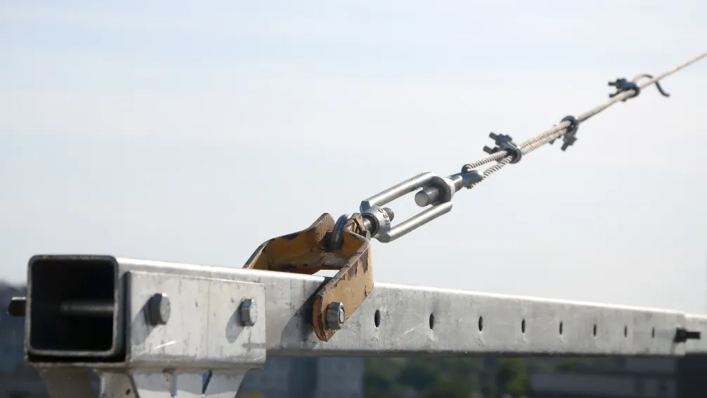
The structural I-beam represents only the foundation of the staging area. The complete mechanical load path includes the diagonal tension components. A twin-ear anchoring lug is typically factory-welded to the top flange near the outer tip of the 16# or 18# beam. This lug accepts a heavy-duty clevis pin.
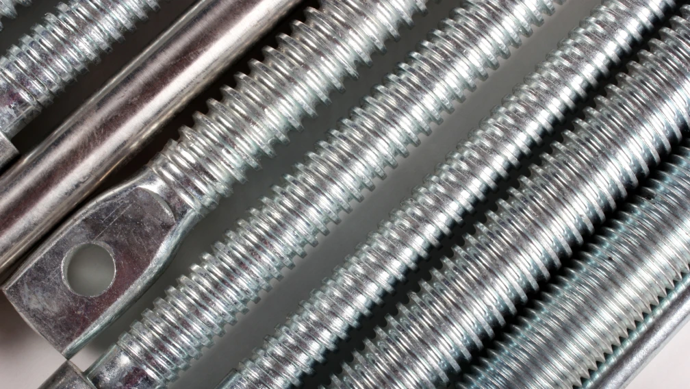
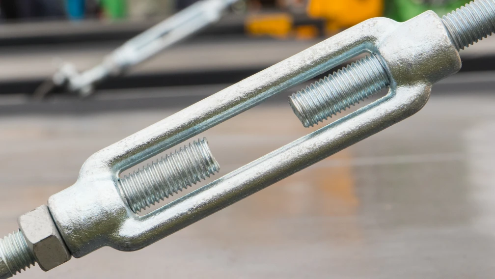
An adjustable tie rod connects to this clevis pin and runs diagonally upward to an embedded anchor in the concrete floor above. Site crews integrate a closed-body turnbuckle into this tension line. By rotating the turnbuckle sleeve, workers remove all physical slack from the tie rod and apply a pre-calculated tension to the system. This action slightly cambers the cantilever beam upward, neutralizing the anticipated downward deflection before any scaffolding materials are stacked onto the platform.
Quality assurance and procurement documentation
Sourcing structural steel for high-rise facades requires a rigorous paper trail to satisfy municipal safety inspectors and project insurance underwriters. B2B buyers must demand full material traceability from their manufacturing partners.
Every shipment of cantilever I-beams must include a Mill Test Certificate (MTC). The MTC details the exact heat number, the chemical composition (carbon, manganese, silicon percentages), and the physical test results (yield strength, tensile strength, and elongation percentage) of the steel batch. For Q235B or Q355B steel designations, the certificate proves the material meets the baseline metallurgical requirements for safe welding and high-stress load bearing. Procuring uncertified steel for critical cantilever scaffolding invites severe legal liabilities and project shutdowns.
Reading the Chinese section nomenclature correctly
The 16# and 18# designations come from the GB/T 706 hot-rolled I-beam series, and the number encodes the section height in centimeters: a 16# beam stands 160 mm tall, an 18# beam 180 mm. Behind the simple label sit the dimensional details that decide structural performance. A standard 16# section carries a web around 6 mm thick, flanges near 88 mm wide, and a theoretical weight of roughly 20.5 kg per meter. The 18# section steps up to a web around 6.5 mm, flanges near 94 mm, and approximately 24.1 kg per meter. That 18 percent increase in weight buys a disproportionately larger gain in bending resistance, because the moment of inertia grows with the cube of the height. In practical terms, moving from 16# to 18# raises the section modulus by roughly 26 percent, which is why the choice between them is a structural calculation and never a pricing afterthought.
Matching the section to the load case
Selection starts from the working platform the beam must carry. For a standard residential facade tier with a 20 m working height, beams spaced at 1.5 m and a projection of 1.2 m or less, the 16# section resolves comfortably under typical load cases of 200 kg per square meter, keeping tip deflection inside the L/250 limit that international codes demand. Push the projection toward 1.8 m, widen the beam spacing to 2 m, or add material staging on the platform, and the bending moment at the fixed end climbs steeply. In that envelope the 18# section becomes the correct answer, carrying the demand without resorting to tighter beam spacing that multiplies anchoring work on every floor. Site engineers deciding between the two should run the numbers on the heaviest intended lift, including the palletized masonry or mortar tubs that crews inevitably park on the platform, because the beam sized for drawings-only loads meets its real test on the first busy morning of the job.
Why section modulus matters more than weight
Procurement teams often compare beams by weight per meter, but the figure that actually controls scaffold performance is the section modulus, which divides the moment of inertia by the distance to the outermost fiber. Two beams of identical weight can differ sharply in modulus if one carries its steel in thin wide flanges and the other in a deep compact profile. The GB/T 706 series is dimensionally fixed, so a genuine 16# beam always delivers its published modulus; the risk enters when suppliers roll substitute sections outside the standard, shaving flange width or web thickness while keeping the label. A quick field check protects the buyer: measure the flange width and web thickness with calipers at three points along a random beam, and weigh a known length on the site scale. A beam that matches nominal dimensions within a percent or two is standard material; one that comes in light across every measurement is rolled to negative tolerance and will underperform the calculation it was sold against.
Connection fit-up: end plates, holes, and pins
A cantilever beam earns its capacity only through its connections, and the fabrication details at the beam ends decide whether the theoretical section performs in the wall. The base end carries a welded end plate or ear plates with holes matched to the embedded anchors, and those holes must be drilled to the anchor pattern with positional accuracy inside a millimeter, or the beams will not seat without site reaming that damages galvanizing and wastes crew hours. The top flange receives welded positioning pins at the standard spacing of the scaffold system, locating each vertical tube exactly over the beam centerline so loads travel straight into the web. Weld quality at these attachments deserves inspection on receipt: continuous fillet welds of the specified leg size, free of undercut and porosity, because a tack-welded pin that snaps under a careless tube drop turns a precision component into a hazard. Reputable fabricators supply the drilling drawing with the quotation, and its dimensions should be checked against the anchor layout before production begins.
Fatigue life and the reuse decision
Cantilever I-beams lead a harder life than most structural steel: they are loaded and unloaded on every floor cycle, handled by crane and by hand, and exposed to weather for the full duration of each project. A well-fabricated beam in Q235B or Q355B survives this treatment for many cycles, but reuse should be a managed decision rather than an assumption. Between projects, each beam merits a five-minute inspection: straightness checked by eye along the flange, welds examined for cracking at the end plate and pins, holes checked for elongation that signals overloading, and coating assessed for rust breakthrough at the connection zones where water sits. Beams showing permanent bow, cracked welds, or oval holes belong in the scrap pile, because the cost of a replacement beam is trivial against the consequence of a failure twenty floors up. Fleets tracked with painted identification numbers let site managers retire individual beams by condition rather than scrapping entire batches on age alone.
Freight economics and container planning
For international buyers, the section choice also changes the logistics arithmetic. Cantilever beams in the 3 to 6 m lengths typical of scaffold work load efficiently into 40-foot containers, and the weight difference between 16# and 18# sections compounds across a full order: a container of 16# beams carries more pieces per ton than the same container of 18#. When the structural calculation permits either section, the lighter choice saves on both steel price and freight per unit of facade served. When the calculation demands 18#, the extra freight cost is simply the price of structural adequacy. Experienced suppliers quote both options with container loading plans, letting the buyer see the total landed cost per beam rather than a bare ex-works figure that hides the freight difference. Mixed containers combining beams with cantilever accessories such as tie rods and anchors usually load most efficiently, filling the cube with hardware while the beams provide the weight.
Documentation that protects the buyer
The paperwork accompanying a cantilever beam order is the buyer's only leverage once the steel is bolted to a wall twenty floors up. A complete documentation package for 16# or 18# beams includes the mill certificate for the parent section, welding procedure and welder qualification records for the end plates and pins, dimensional inspection reports against the approved drilling drawing, and coating thickness readings where galvanizing is specified. Buyers who receive shipments without this trail have no recourse when a beam underperforms, because the dispute collapses into assertion against denial. The practical rule is to make documentation a payment condition: mill certificates before shipment, fabrication records with the bill of lading, and third-party inspection reports where the order value justifies the fee. Suppliers with genuine quality systems produce this paperwork as a matter of routine, and their willingness to do so is itself a selection signal worth more than a marginal price difference.
Frequently asked questions
What dictates the choice between a 16# and 18# cantilever I-beam?
The choice is dictated by the projected span of the cantilever and the maximum intended working load. 16# beams serve standard residential perimeters with short spans, while 18# beams provide the higher section modulus required for heavy material staging, wider spans, and high wind-shear zones.
What does negative tolerance mean when buying structural I-beams?
Negative tolerance refers to the steel mill rolling the web and flanges slightly thinner than the nominal standard dimension. While minor negative tolerances are acceptable under international codes, excessive negative tolerance severely compromises the beam's load capacity. Buyers must specify strict tolerance limits in purchasing contracts.
Why are scaffold positioning pins welded to cantilever I-beams?
Positioning pins (spigots) are welded to the top flange to act as exact locating points for the vertical scaffold tubes. They prevent the base of the scaffold structure from sliding laterally along the smooth steel flange under wind loads or worker movement, ensuring total system stability.
What is the maximum allowable deflection for a cantilever scaffolding beam?
Under international building codes such as OSHA, the vertical downward deflection at the tip of the cantilever beam must not exceed L/250 of the projecting length. Excessive deflection causes eccentric loading on the vertical scaffolding frames and creates a major collapse risk.
Can I substitute a 16# I-beam for an 18# beam if I add more tie-rods?
No. While adding tie-rods reduces the bending moment at the base anchor, the physical steel section must still possess enough raw stiffness to prevent localized web buckling and handle the point loads of the vertical tubes. Always adhere to the structural engineer's exact section specifications.
What steel grade is standard for these cantilever I-beams?
Standard perimeter outriggers are typically manufactured from Q235B carbon structural steel due to its excellent weldability and ductility. For heavy-duty engineering applications or extremely cold climates, engineers specify Q355B low-alloy high-strength steel for superior yield capacity.
How are these beams protected against rust on coastal construction sites?
Hot-dip galvanizing (HDG) is the specified surface treatment for heavy-duty construction components. The process applies a thick, metallurgically bonded zinc layer (typically 80 microns or thicker) that resists mechanical impact and completely prevents oxidation in humid and salt-fog environments.
Connect with our engineering team for custom section cutting
Lengge Steel manufactures certified cantilever scaffolding systems, delivering prefabricated 16# and 18# cantilever I-beams, heavy-duty H-section supports, and complete tension anchoring hardware to global jobsites. We provide exact cut-to-length services, factory-welded positioning pins, precision CNC anchor drilling, and premium hot-dip galvanizing. Supply our engineering desk with your project setbacks and loading requirements to receive a comprehensive hardware schedule and a wholesale structural quotation. Visit our contact page to optimize your next high-rise scaffolding inventory.
-

Lengge
Cantilever Scaffolding System Manufacturer
Lengge is a China-based factory producing cantilever I-beams, tie rods, couplers, embedded parts and full scaffolding accessories. We supply contractors, wholesalers and rental companies in over 50 countries from our own production facility in Hebei.